Time Dependent Dielectric Breakdown Test Structure and Test Method Thereof

Active Publication Date: 2020-05-07
YANGTZE MEMORY TECH CO LTD
View PDF0 Cites 3 Cited by
  • Summary
  • Abstract
  • Description
  • Claims
  • Application Information

AI Technical Summary

Benefits of technology

[0005]It is therefore an objective of the present invention to provide a time dependent dielectric breakdown test str

Problems solved by technology

However, TDDB test takes a long time for one-by-one test.
However, in

Method used


Image

  • Time Dependent Dielectric Breakdown Test Structure and Test Method Thereof
  • Time Dependent Dielectric Breakdown Test Structure and Test Method Thereof
  • Time Dependent Dielectric Breakdown Test Structure and Test Method Thereof

Examples


Embodiment Construction

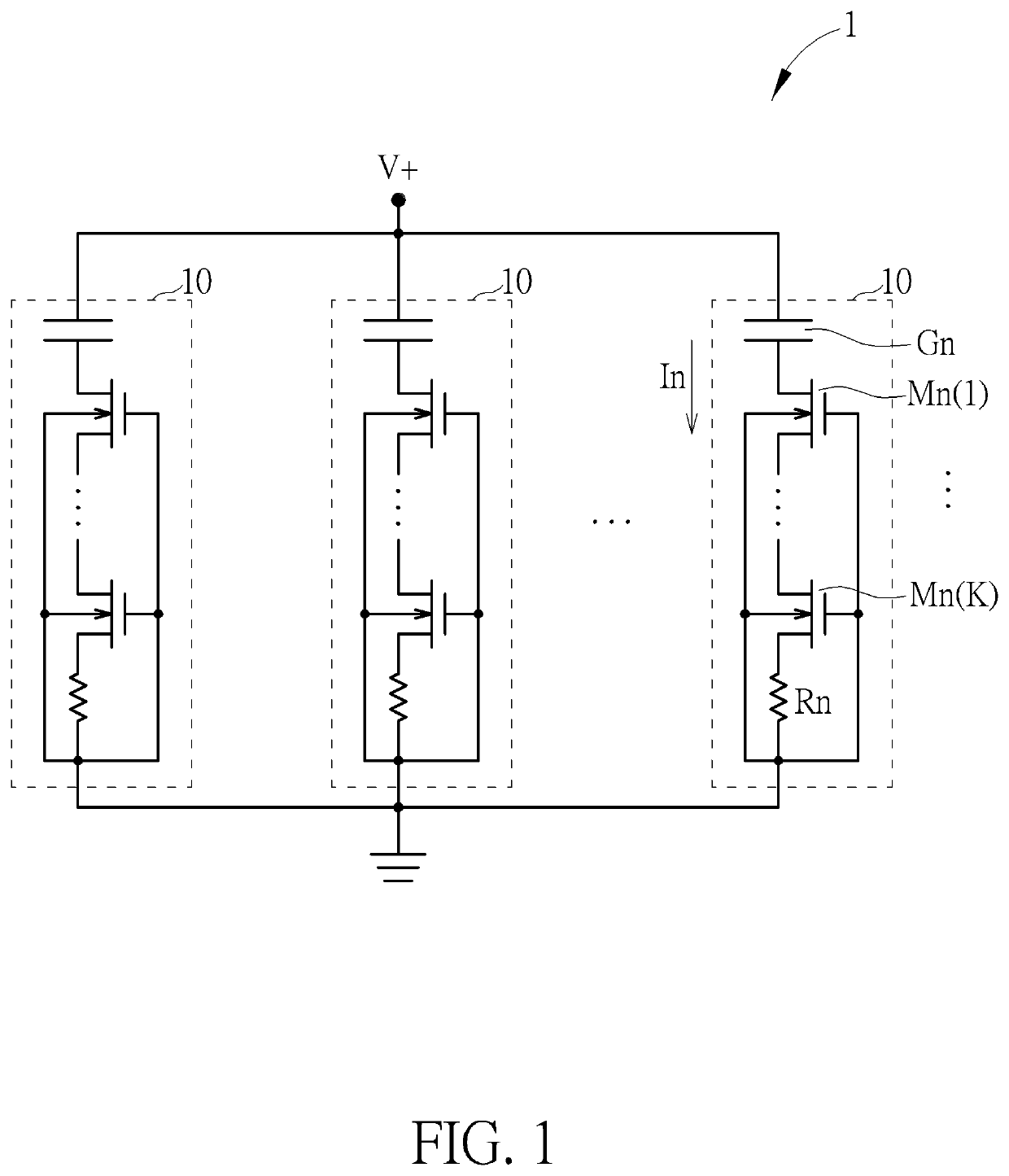
[0019]FIG. 1 is a schematic diagram of an N-type TDDB (Time Dependent Dielectric Breakdown) test structure 1 according to an embodiment of the present invention. The N-type TDDB test structure 1 includes a plurality of N-type test units 10 connected in parallel between a constant positive voltage V+ and a ground.

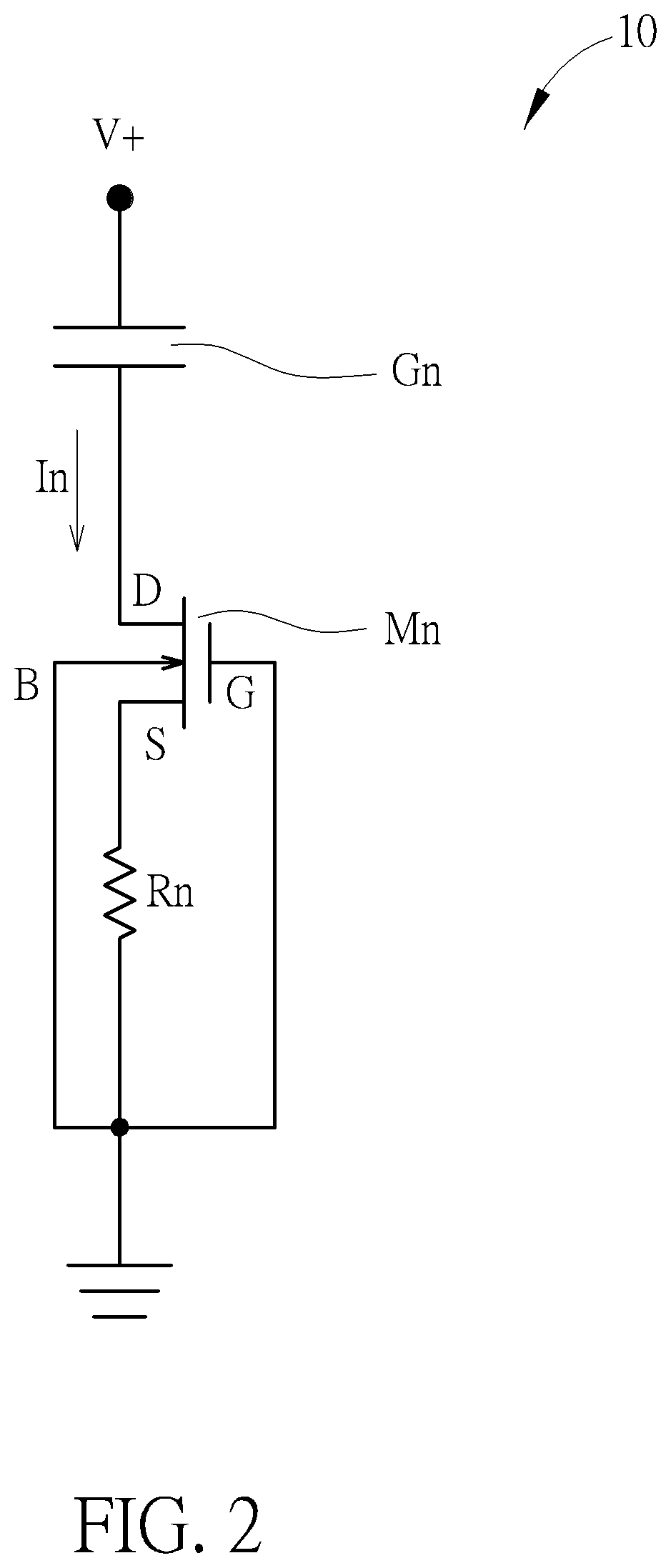
[0020]Each of the plurality of test units 10 is structurally identical and includes a dielectric test sample Gn and a current restraint unit. The dielectric test sample Gn is connected between the constant positive voltage V+ and the current restraint unit. The current restraint unit includes at least one DEPFET (depleted field effect) transistor and a resistor Rn.

[0021]Given that the current restraint unit includes a plurality of DEPFET transistors Mn(1)˜Mn(K) serially connected with each other between the dielectric test sample Gn and the resistor Rn. The plurality of DEPFET transistors Mn(1)˜Mn(K) corresponds to a plurality of negative threshold voltages Vtn(1)˜Vtn(K), re...


PUM


Abstract

A time dependent dielectric breakdown test structure includes a plurality of test units connected in parallel between a constant voltage and a ground. Each of the plurality of test units includes a dielectric test sample connected to the constant voltage; and a current restraint unit connected between the dielectric test sample and the ground, for restraining a breakdown current from flowing on the dielectric test sample after the constant voltage has broken the dielectric test sample.

Description

CROSS REFERENCE TO RELATED APPLICATIONS[0001]This is a continuation application of International Application No. PCT / CN2018 / 114143 filed on Nov. 6, 2018, which are incorporated herein by reference in its entirety.BACKGROUND OF THE INVENTION1. Field of the Invention[0002]The present invention relates to a time dependent dielectric breakdown test structure and test method thereof, and more particularly, to a time dependent dielectric breakdown test structure and test method thereof with current restraint unit.2. Description of the Prior Art[0003]In integrated circuit manufacturing, reliability assessment is an important part of process development. TDDB (Time Dependent Dielectric Breakdown) test is an important method to evaluate the reliability of dielectric materials, e.g., gate oxide of semiconducting transistor. However, TDDB test takes a long time for one-by-one test. In general, in order to ensure that the test results have certain statistical significance, a TDDB test condition...

Claims


Application Information

Patent Timeline
IPC IPC(8): G01R31/14
CPCG01R31/129G01R31/14H01L22/14G01R31/1263H01L22/34G01R31/2858
Inventor YANG, SHENGWEIHAN, KUN
Owner YANGTZE MEMORY TECH CO LTD
Why Eureka
Try Eureka