Scroll type micro-compressor, and method for machining fixed scroll plate and orbit scroll plate thereof
- Summary
- Abstract
- Description
- Claims
- Application Information
AI Technical Summary
Benefits of technology
Problems solved by technology
Method used
Image

Examples
Embodiment Construction
[0049]The technical solutions in the embodiments of the present disclosure will be described clearly and completely as follows with reference to the drawings in the embodiments of the present disclosure. Obviously, those described are merely parts, rather than all, of the embodiments of the present disclosure. Based on the embodiments of the present disclosure, any other embodiment obtained by those skilled in the art without paying any creative labor should fall within the protection scope of the present disclosure.
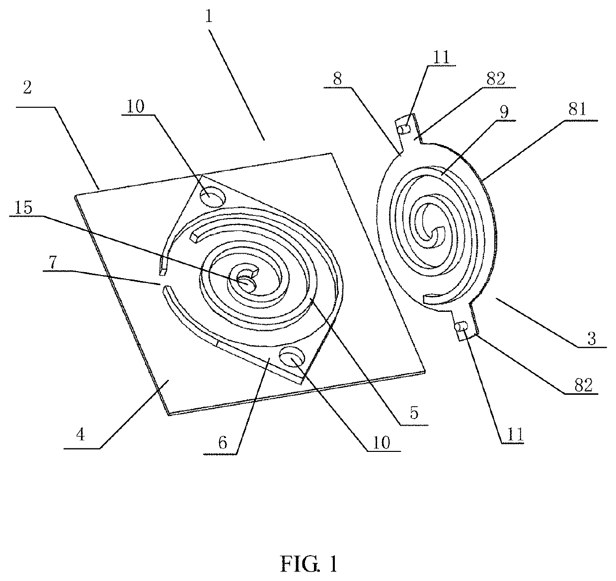
[0050]As shown in FIGS. 1, 4 and 5, the present disclosure proposes a scroll type micro-compressor 1 which is based on a monocrystalline silicon substrate and electrostatically driven, comprising a fixed scroll plate 2 and an orbit scroll plate 3 each integrally made with a monocrystalline silicon substrate to reduce the cost. As shown in FIG. 1, the fixed scroll plate 2 comprises: a fixed scroll plate substrate 4, a fixed scroll wall 5 and an annular shell 6 located out...
PUM
| Property | Measurement | Unit |
|---|---|---|
| Thickness | aaaaa | aaaaa |
| Mass | aaaaa | aaaaa |
| Shape | aaaaa | aaaaa |
Abstract
Description
Claims
Application Information
 - Generate Ideas
- Intellectual Property
- Life Sciences
- Materials
- Tech Scout
- Unparalleled Data Quality
- Higher Quality Content
- 60% Fewer Hallucinations
Browse by: Latest US Patents, China's latest patents, Technical Efficacy Thesaurus, Application Domain, Technology Topic, Popular Technical Reports.
© 2025 PatSnap. All rights reserved.Legal|Privacy policy|Modern Slavery Act Transparency Statement|Sitemap|About US| Contact US: help@patsnap.com