Sound Generator

Active Publication Date: 2020-05-14
AAC ACOUSTIC TECH (SHENZHEN) CO LTD
View PDF0 Cites 0 Cited by
  • Summary
  • Abstract
  • Description
  • Claims
  • Application Information

AI Technical Summary

Benefits of technology

The present patent provides a sound generator with a diaphragm that has a sealed cavity and a dual-suspension made of high elasticity materials. This configuration improves the strength of the vibration system and solves the issue of membrane shrunken. The diaphragm is protected from breaking. The "dual suspension" effectively broades the linear range of the vibration system and reduces the total harmonic distortion of the sound generator, especially for a large sound pressure level. The use of a top cover further improves the combination strength and waterproof grade. The second part of the suspension increases the effective vibration area of the diaphragm, which enhances the high-frequency performance and makes it a key component of gesture recognition.

Problems solved by technology

In such a configuration, the combination strength of the dome and the suspension is weak, and a phenomenon called “membrane shrunken” will appear when the sound generator is used in a condition requiring deep-water resistance, which will cause the diaphragm to be broken.
In addition, liner range of such a vibration system is narrow, which will lead to total harmonic distortion, and to bad high frequency performance.

Method used


Image

  • Sound Generator
  • Sound Generator
  • Sound Generator

Examples


embodiment 1

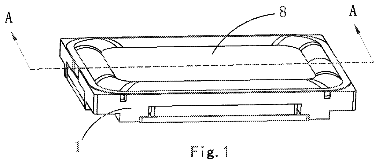
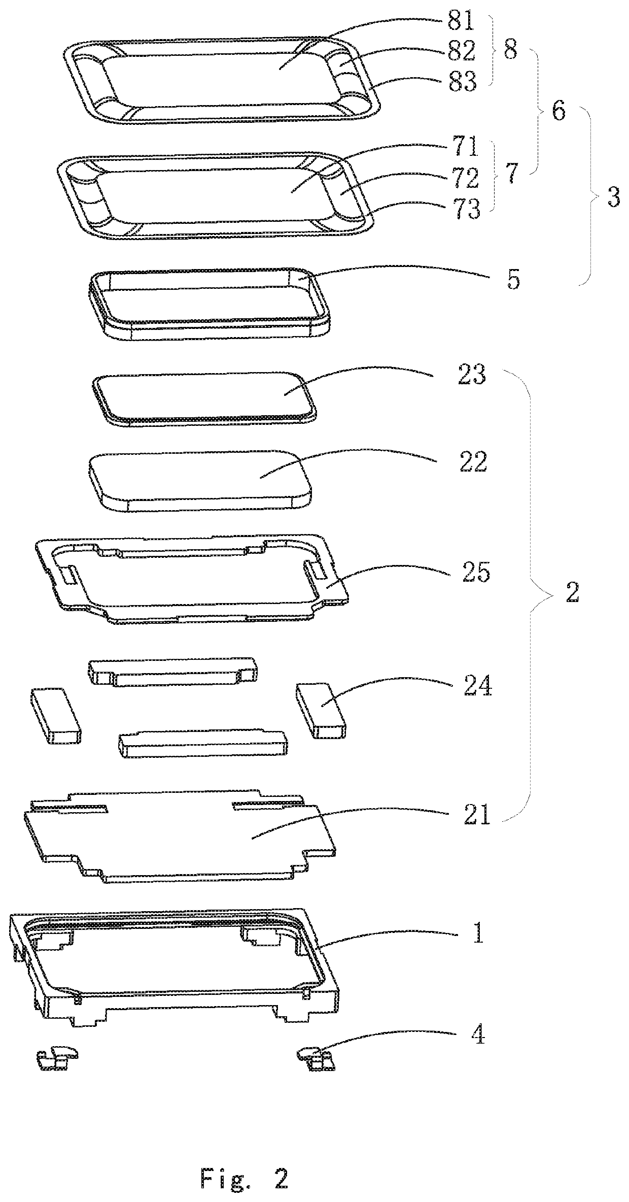
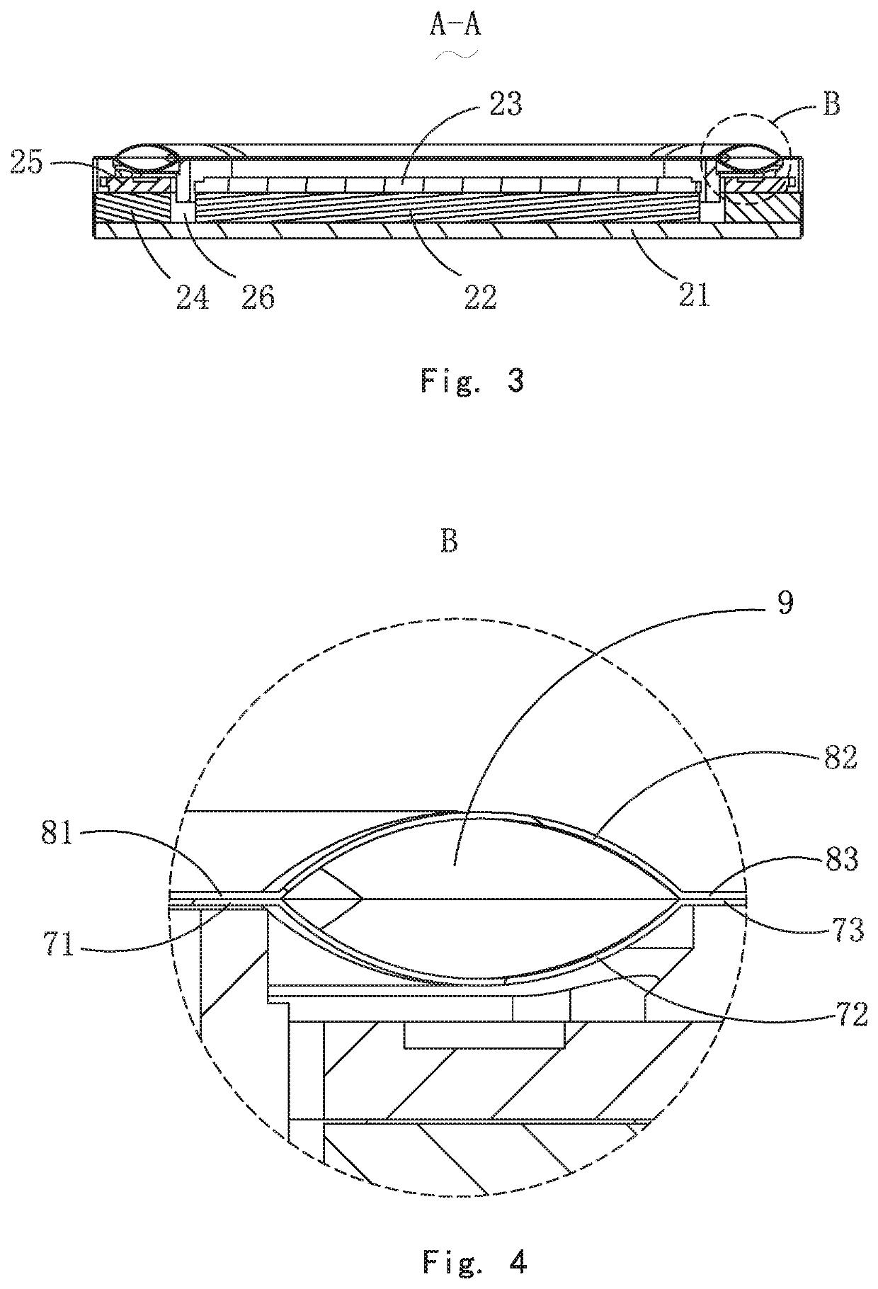
[0017]Referring to FIGS. 1-4, a sound generator in accordance with a first exemplary embodiment of the present disclosure is disclosed. The sound generator includes a frame 1, a magnetic circuit system 2 and a vibration system 3 accommodated in the frame 1, and a plurality of conductive terminals 4 assembled with the frame 1. The vibration system 3 includes a voice coil 5 and a suspension 6 attached to the frame 1 and connected with the voice coil 5. The magnetic circuit system 2 includes a magnetic yoke 21, a main magnet 22 mounted with the magnetic yoke 21, a pole plate 23 attached to a top of the main magnet 22, a plurality of auxiliary magnets 24 disposed around the main magnet 22, and an upper plate 25 attached to the auxiliary magnets 24. A magnetic gap 26 is formed between the main magnet 22 and the auxiliary magnets 24.

[0018]Referring to FIGS. 2-4, the suspension 6 includes a first part 7 connected to the frame 1 and a second part 8 attached to the first part 7. The first pa...

embodiment 2

[0019]Referring to FIGS. 5-7, a sound generator in accordance with a second exemplary embodiment of the present disclosure is disclosed. The sound generator in the second embodiment is basically same to the sound generator in the first embodiment. The differences therebetween are that the frame 1′ is coupled with a top cover 10 having a top cover body 101 and a metal plate 102 embedded in the top cover body 101. The first positioning portion 73′ is adhered to the second positioning portion 83′ then they are sandwiched between the frame 1′ and the top cover 10. The second edge portion 82′ is convex far away from the frame 1′ and forms a first height H1, and the first edge portion 72′ is convex toward the frame 1′ and forms a second height H2. The first height H1 is smaller than the second height H2. The first part 7′ is formed by TPEE (Thermoplastic Polyether Ester Elastomer). The second part 8′ is a three-layer-structure including a layer of TPEE, a layer of carbon fiber, and a laye...

embodiment 3

[0023]Referring to FIGS. 8-11, a sound generator in accordance with a third embodiment of the present disclosure is disclosed. The differences form the first embodiment are that the frame 1″ is coupled with a top cover 10′ having a top cover body 101′ and a metal plate 102′ embedded in the top cover body 101′. The first positioning portion 73″ is adhered to the second positioning portion 83″ then are sandwiched between the frame 1″ and the top cover 10′. The vibration system 3″ further includes a dome 11 attached to the second middle portion 81″ of the second part 8″. The first part 7″ is provided with one or two layers adhered to each other and formed by PEEK (Polyether-ether-ketone). The second part 8″ is formed by TPEE (Thermoplastic Polyether Ester Elastomer). The configuration of dual-suspension made of high elasticity materials improves the strength of the vibration system. The dome is made of alloy materials selected from aluminum alloy, magnesium alloy, magnesium lithium all...


PUM


Abstract

A sound generator includes a frame, a magnetic circuit system and a vibration system accommodated in the frame. The vibration system includes a suspension. The suspension includes a first part and a second part attached to the first part. The first part includes a first middle portion, a first edge portion, and a first positioning portion. The second part includes a second middle portion, a second edge portion, and a second positioning portion. The second positioning portion is stacked on the first positioning portion, and is assembled with the first positioning portion by adhesive. The first edge portion is convex toward the frame, and the second edge portion is convex away from the frame, by which a sealed cavity is formed between the first and second edge portions. By virtue of such a configuration, the strength of the vibration system is improved.

Description

FIELD OF THE PRESENT DISCLOSURE[0001]The present disclosure relates to the field of electro-magnetic transducers, more particularly to a sound generator and a diaphragm used in the sound generator.DESCRIPTION OF RELATED ART[0002]A sound generator, also named speaker, is a very important component equipped in a mobile phone for producing audible sounds. A speaker generally uses a diaphragm to produce vibration and further to generate sounds. The diaphragm is a key factor to determine the performance of the sound generator. In a related sound generator, a frame is provided, and the sound generator further includes a magnetic circuit system and a vibration system accommodated in the frame. The vibration system includes a suspension mounted with the frame and a dome attached to a central portion of the suspension. In such a configuration, the combination strength of the dome and the suspension is weak, and a phenomenon called “membrane shrunken” will appear when the sound generator is u...

Claims


Application Information

Patent Timeline
IPC IPC(8): H04R7/10H04R7/16H04R7/12H04R31/00
CPCH04R31/003H04R7/127H04R2307/029H04R2307/023H04R7/16H04R7/10H04R2307/025H04R2499/11H04R7/18H04R9/025H04R2231/001H04R2231/003H04R2307/204H04R2307/207
Inventor XIAO, BOLINGHU, RONGLIN
Owner AAC ACOUSTIC TECH (SHENZHEN) CO LTD
Why Eureka
Try Eureka