Inert gas generator for an inerting system of an aircraft system of an aircraft fuel tank, and inerting method

a technology of inerting system and aircraft fuel tank, which is applied in the direction of chemistry apparatus and processes, separation processes, dispersed particle separation, etc., can solve the problems of increasing the weight, consumption and cost of the inerting system during these flight phases, and achieve the effect of reducing its consumption and cost of us

Active Publication Date: 2020-05-28
SAFRAN AEROTECHNICS SAS
View PDF0 Cites 6 Cited by
  • Summary
  • Abstract
  • Description
  • Claims
  • Application Information

AI Technical Summary

Benefits of technology

[0008]One of the objectives of the disclosed embodiments is therefore to overcome the disadvantages of the prior art by providing an inert gas generator, as well as an inerting method, that optimizes the size and use of an inerting system in order to reduce its consumption and cost of use.
[0012]In this way, use of the air separation modules is linked to the actual requirement for inert gas, which requirement is notably determined by the flight phase of the aircraft. Thus, the inert gas generator consumes the quantity of air needed to meet the requirement for inert gas. All overconsumption is avoided. The disclosed embodiments thus enable the operating costs of the system and the inert gas generator to be reduced, and also reduces wear and tear, thus increasing the life span of the components in the inert gas generator.
[0022]In this configuration, the embodiments can switch between the various air separation modules, after a specified period of use, to even out wear and tear of the various air separation modules, for example by switching to the following modules, the best-performing modules or the modules with the lowest number of accumulated operating hours.
[0023]Thus, the use and wear and tear of the various air separation modules can be evened out.

Problems solved by technology

The same applies to the filter elements and other components of the inerting system, which increases the weight, consumption and cost of the inerting system during these flight phases.

Method used


Image

  • Inert gas generator for an inerting system of an aircraft system of an aircraft fuel tank, and inerting method
  • Inert gas generator for an inerting system of an aircraft system of an aircraft fuel tank, and inerting method
  • Inert gas generator for an inerting system of an aircraft system of an aircraft fuel tank, and inerting method

Examples


Embodiment Construction

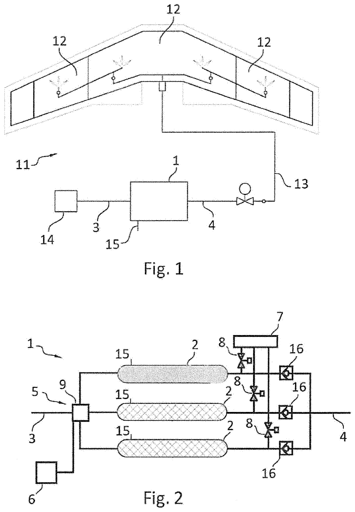
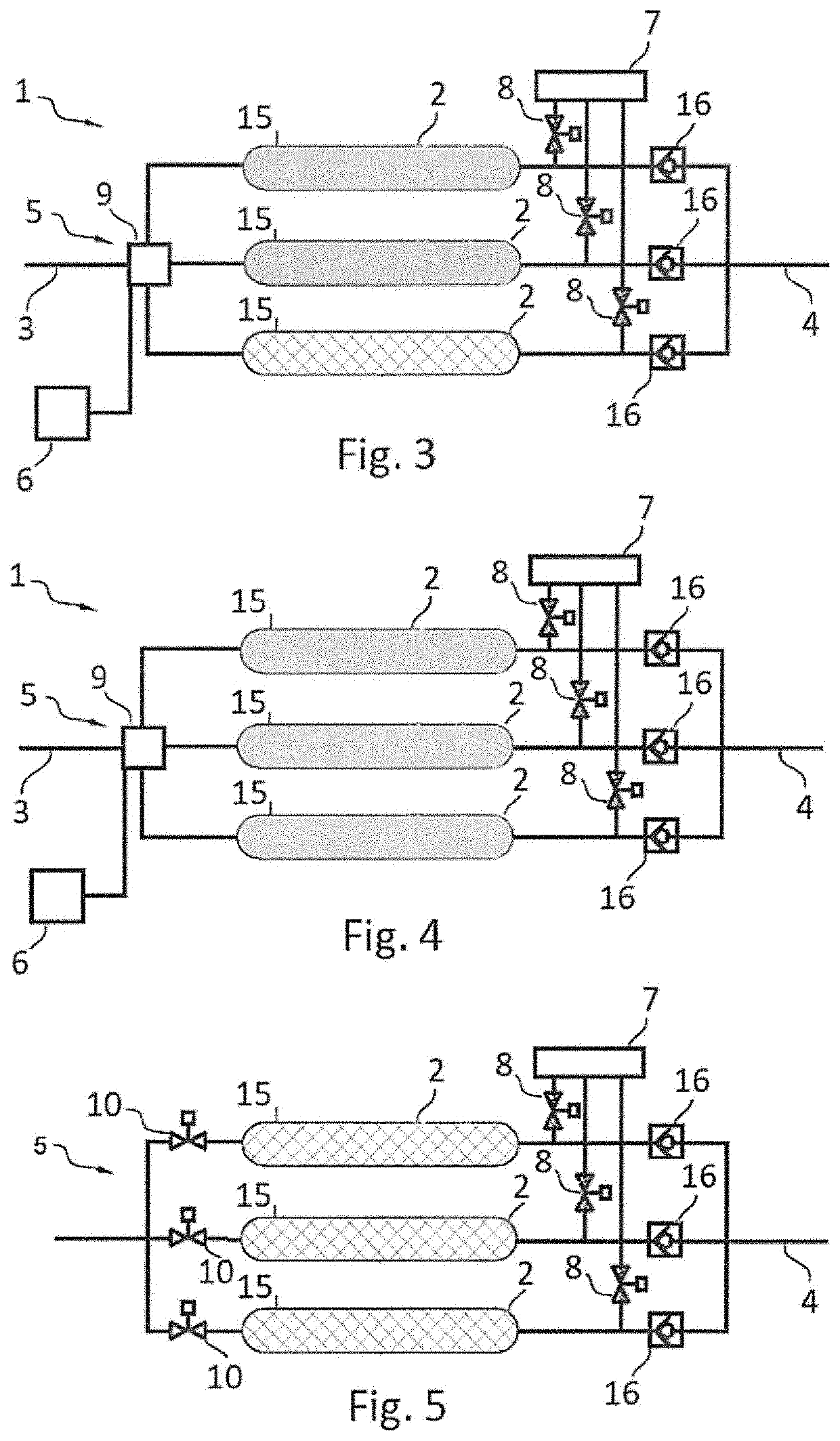
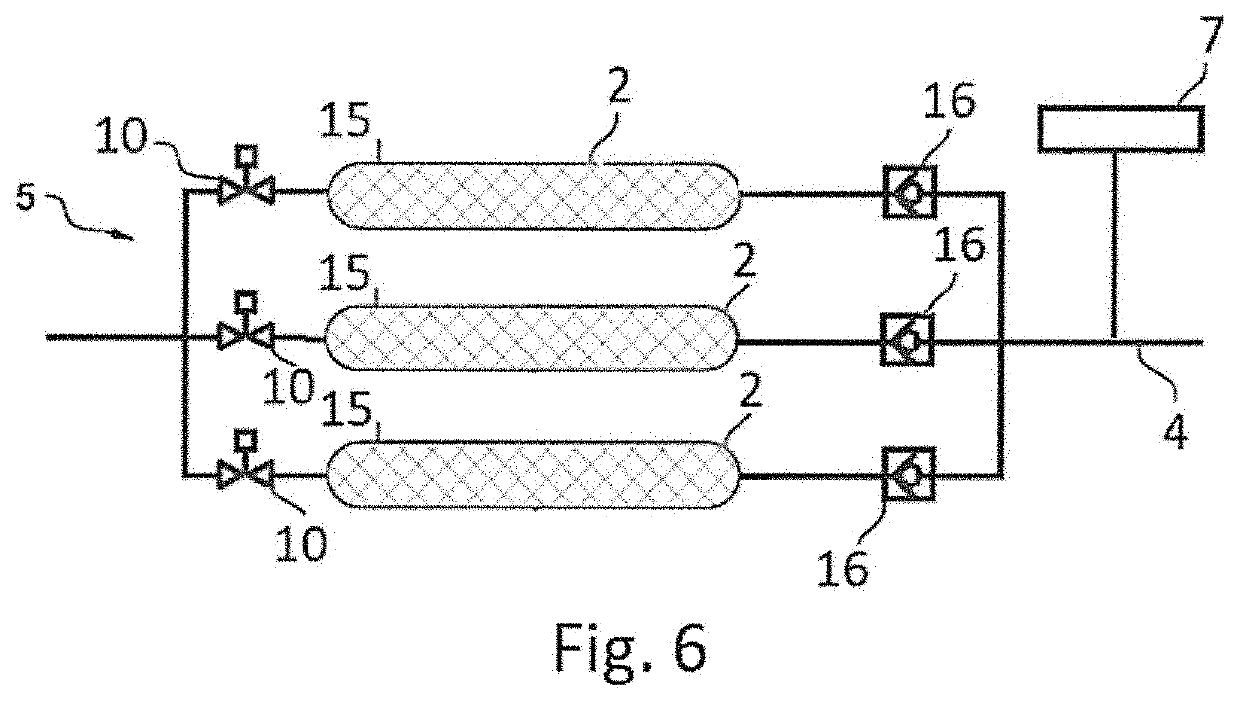
[0036]With reference to FIG. 1, the disclosure relates to an inert gas generator (1) comprising an air system (2) to deplete oxygen in order to generate a nitrogen-enriched inert gas.

[0037]The generator (1) is notably intended to be used in an inerting system (11) for at least one aircraft fuel tank (12). To this end, the inert gas generator (1) comprises an air inlet (3) supplied with bleed air diverted from at least one engine and / or air from a passenger cabin and / or air from outside the aircraft via an air preparation system (14) that may be subjected to a compressor, and an inert gas outlet (4) connected to insert gas distribution means (13) in the fuel tank(s) (12). The generation system (1) also comprises an oxygen-enriched gas outlet (15).

[0038]The inerting system (11) allows an inert gas to be generated and introduced into said aircraft fuel tank(s) (12) for safety reasons in order to reduce the risk of explosion of said tanks. The injected inert gas aims to render the fuel ...


PUM


Abstract

A generator of inert gas from an airflow, in an inerting system for at least one aircraft fuel tank is disclosed. The generator includes a system with an air inlet and means for distributing the airflow to a plurality of air separation modules arranged in parallel on the air system to deplete oxygen in the air and generate a nitrogen-enriched inert gas at the outlet. The generator also includes a programed control unit for the distribution means to selectively supply air to a single, a portion or all of the air separation modules, depending on the flight phase of the aircraft.

Description

TECHNICAL FIELD[0001]This disclosure relates to the art of inert gas generation systems, notably used in inerting systems for at least one fuel tank of an aircraft such as an airplane, a helicopter or similar.BACKGROUND OF THE DISCLOSURE[0002]In the field of aeronautics, the use of inerting systems is well known to generate an inert gas, such as nitrogen or any other inert gas such as carbon dioxide, and for injecting said inert gas into fuel tanks for safety reasons in order to reduce the risk of explosion of said tanks.[0003]Generally speaking, an inert gas generator comprises a system with an air inlet and the means for distributing the airflow to a plurality of air separation modules arranged in parallel on the air system to deplete oxygen in the air and generate a nitrogen-enriched inert gas at the outlet.[0004]Current inerting systems enable inert gas whose level of inflammability is incompatible with the certification rules in the field of aviation, which are well-known to a ...

Claims


Application Information

Patent Timeline
Patent Type & Authority Applications(United States)
IPC IPC(8): B01D53/30B01D53/22B64D37/32
CPCB01D53/227B01D53/30B64D37/32B01D2053/221B64D2013/0677B64D2013/0681B64D2045/0085B01D2259/4575B01D2257/104B01D2256/10Y02T50/40
Inventor CLARIS, CHRISTOPHE
Owner SAFRAN AEROTECHNICS SAS
Why Eureka
Try Eureka