
Production of biomethane using multiple types of membrane

a technology of biomethane and membrane, which is applied in the direction of gaseous fuels, hydrocarbon purification/separation, hydrocarbons, etc., can solve the problems of large fraction of methane and other obnoxious contaminants in the exhaust gas that survive, and the methane that escapes into the ambient air becomes a source of air pollution

Inactive Publication Date: 2020-06-11
AIR LIQUIDE ADVANCED TECH U S
View PDF1 Cites 0 Cited by
  • Summary
  • Abstract
  • Description
  • Claims
  • Application Information

AI Technical Summary

Benefits of technology

The system effectively produces biomethane with at least 94% methane, low levels of impurities, and meets safety criteria for utility pipeline delivery, reducing costs and energy consumption by eliminating the need for regenerable adsorbent beds and pre-conditioning facilities.

Problems solved by technology

If digester and landfill exhaust gas is not recovered, the methane that escapes into ambient air becomes a source of air pollution.
This burning process is inefficient, and consequently, a large fraction of the methane and other obnoxious contaminants in the exhaust gas survive to pollute the ambient air.
Also, common flare stack operations are a waste of the useful energy held by the methane in the exhaust gas.
Unfortunately, the adsorbent particles in the PSA / TSA units ultimately become saturated with the contaminants, and lose their abilities to adsorb beyond a maximum amount.
Thus, it is very costly in financial and energy consumption aspects to operate conventional adsorption-regeneration technologies, to recover useful methane from digester and landfill exhaust gas.
However, the selectivity and permeance of the membranes prepared from those materials often quickly decrease, once they are used for methane gas extraction in the presence of VOC's and other biogas impurities.
This loss of membrane performance is caused by condensation and coating of the VOC's and siloxanes on the membrane surface or due to adsorption of the heavy components in the membrane fiber.
Although these pretreatment systems can effectively remove VOC's and other components from the biogas stream, the cost of the pretreatment and / or frequent membrane replacement can be prohibitive.
Indeed, the cost of the pretreatment system can be as high as 50% of the total system cost (pretreatment plus membrane).
However, the system in '803 is relatively costly for some system operators and does not satisfactorily handle relatively high levels of H2S.

Method used


Image

  • Production of biomethane using multiple types of membrane
  • Production of biomethane using multiple types of membrane
  • Production of biomethane using multiple types of membrane

Examples


Embodiment Construction

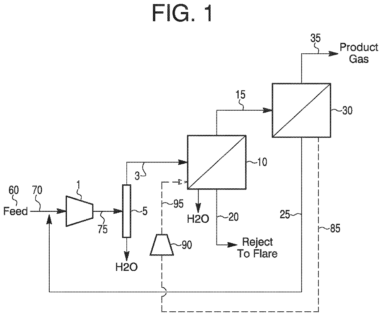
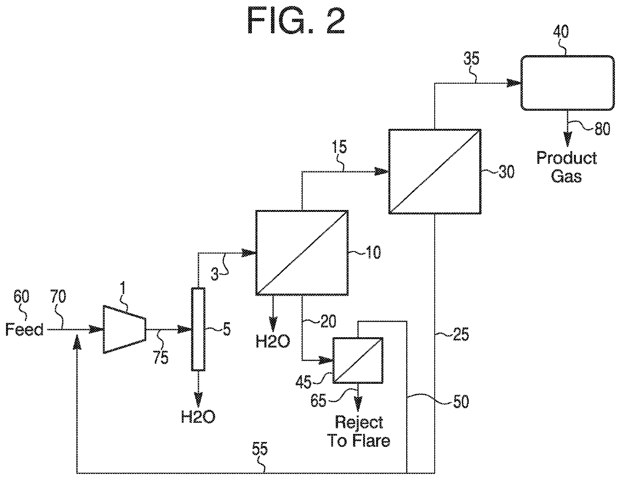
[0067]There is a disclosed method for producing biomethane from biogas, comprising: compressing a stream of the biogas in a compressor; removing water from the compressed feed by cooling; and sending the dehydrated and compressed feed into a first separation stage containing at least one polymeric gas separation membrane having a selectivity of at least 10, preferably at least 30, for H2S over CH4 to permeate a first low quality gas mixture having less than 20% methane and impurities such as H2S, water, siloxane, CO2, and VOC's, then passing the retentate or first gas mixture, having at least 60% methane from the first separation stage, to a second separation stage containing at least one polymeric gas separation membrane having a selectivity of at least 20, preferably at least 35, for CO2 over CH4 to produce a biomethane having at least 94% methane, below 3% of CO2, below 100 ppm of H2S, below 100 ppm of VOC's, below 100 ppm of siloxanes, and below 0.01 wt. % of water.

[0068]The mem...


PUM


Abstract

The invention relates to a process for recovering methane from digester biogas or landfill gas. More specifically, the invention pertains to a method for producing biomethane that removes impurities from a compressed digester biogas with staged membrane modules of at least two different types, to produce a biomethane having at least 94% CH4, below 3% of CO2, and below 4 ppm of H2S.

Description

CROSS REFERENCE TO RELATED APPLICATIONS[0001]The present application is a continuation application of U.S. application Ser. No. 15 / 711,571 filed Sep. 21, 2017, which is being incorporated by reference herein in its entirety for all purposes.FIELD OF THE INVENTION[0002]The invention pertains to biomethane production by processing compressed biogas through multiple membrane stages, wherein at least two membrane stages have different membrane types.BACKGROUND OF THE INVENTION[0003]Biogas typically refers to a mixture of different gases produced from the breakdown of organic matter without oxygen in an anaerobic digestion process. Biogas can be produced from raw materials such as agricultural waste, manure, municipal waste, plant material, sewage, green waste or food waste. Biogas typically comprises as the main components 50-70% of methane (“CH4”) and 20 to 50% carbon dioxide (“CO2”), with lower levels of other components such as N2 and O2, up to 5,000 ppm or more of hydrogen sulfide (...

Claims


Application Information

Patent Timeline
Patent Type & Authority Applications(United States)
IPC IPC(8): B01D53/22C10L3/10C07C7/00C07C7/144B01D71/80B01D53/26B01D69/12B01D69/10
CPCB01D53/265B01D2317/08C10L3/106C07C7/144C10L3/103C10L2290/26B01D2257/102C10L2290/545B01D2319/022B01D69/10B01D71/52C10L2290/46B01D2256/245B01D71/56B01D71/80C10L2290/548B01D2257/304C10L2290/10B01D69/12C10L3/105B01D2257/104C10L3/101B01D2257/55C07C7/005C10L3/104B01D53/228B01D53/268B01D2257/708B01D2258/05B01D2257/504B01D53/226Y02C20/40Y02E50/30Y02P20/151B01D71/5211B01D69/107B01D71/5222C07C9/04
Inventor DING, YONGMITARITEN, MICHAEL J.
Owner AIR LIQUIDE ADVANCED TECH U S
Features
  • Generate Ideas
  • Intellectual Property
  • Life Sciences
  • Materials
  • Tech Scout
  • Unparalleled Data Quality
  • Higher Quality Content
  • 60% Fewer Hallucinations
Learn More