High performance cable termination

a high-performance, cable technology, applied in the direction of fixed connections, coupling device connections, printed circuit aspects, etc., can solve problems such as reducing signal integrity

Active Publication Date: 2020-06-18
AMPHENOL CORP
View PDF0 Cites 14 Cited by
  • Summary
  • Abstract
  • Description
  • Claims
  • Application Information

AI Technical Summary

Problems solved by technology

Non-uniformities on a signal path, such as might be created by changes in shape or material of the components, give rise to changes in impedance or promote mode conversion, which reduce signal integrity, as these effects are manifested as insertion loss, crosstalk or other undesirable effects.

Method used


Image

  • High performance cable termination
  • High performance cable termination
  • High performance cable termination

Examples


Embodiment Construction

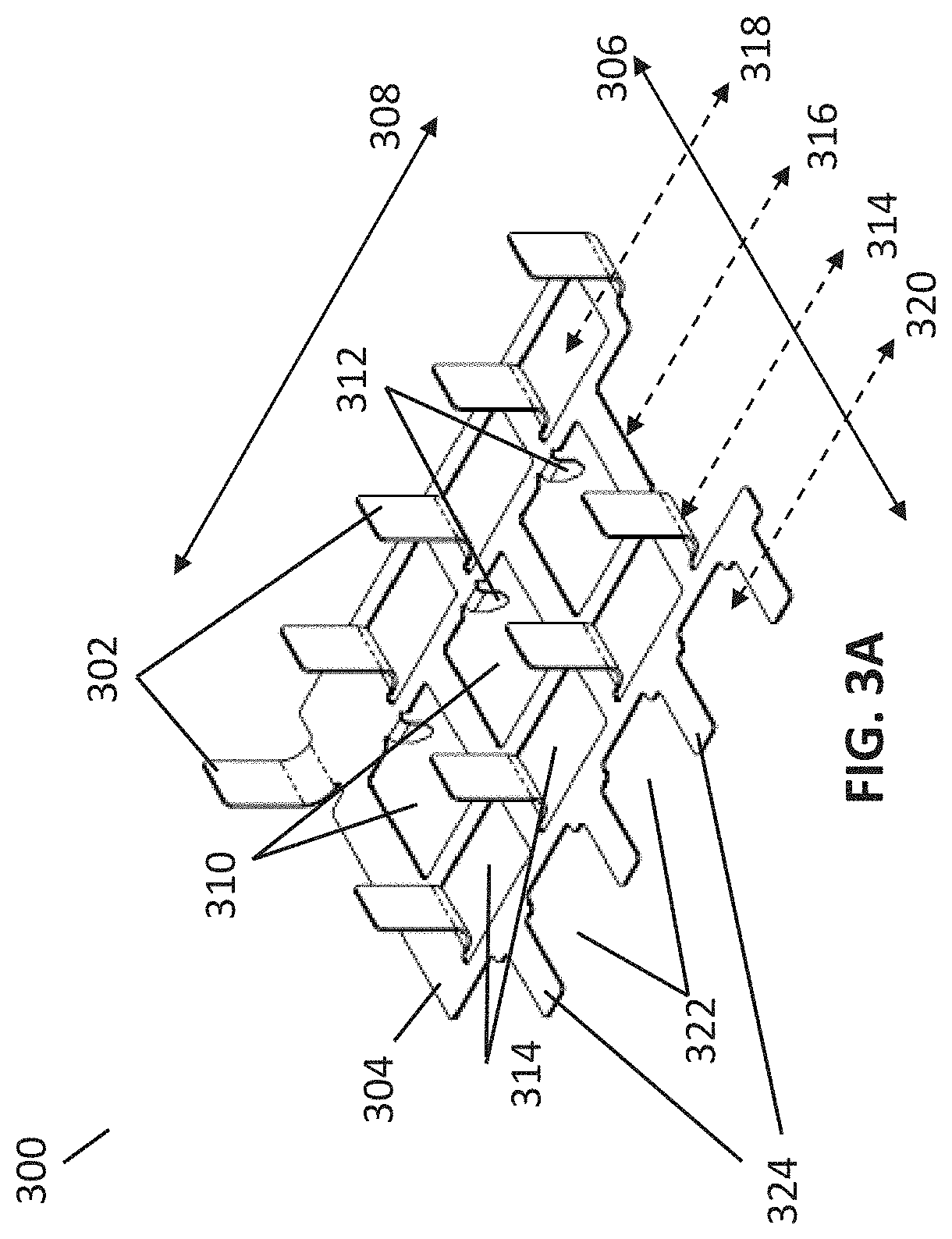
[0039]The inventors have recognized and appreciated structures for providing a high frequency, compact cable assembly. The structures may include a conductive structure, such as one or more straps, which includes a plurality of tabs that are configured for electrical contact with an exposed shield of an associated cable of the high frequency compact cable assembly. The conductive structure may be physically mounted to a surface of a printed circuit board (PCB), such that each tab extends upward from the surface of the PCB. The PCB may be a paddle card of a connector, and may include multiple pads at least partially disposed on the surface, such that at least one conductive structure is electrically and physically connected to some of the pads.

[0040]The conductive structure may be electrically connected to a ground structure within the PCB, providing conductive paths between shields of the cables and the ground structure within the PCB. In some embodiments, the conductive structure m...


PUM


Abstract

A cable assembly comprising a connector with a termination that enables high density and high signal integrity. Shields of cables are terminated to a paddle card via a conductive structure attached to a surface of the paddle card. The signal conductors of the cables are terminated to pads on the paddle card that are exposed within openings of the conductive structure. Such a structure creates a ground structure per cable that provides low insertion loss and low crosstalk, even when multiple cables are aligned side by side and terminated in one or more rows. The cables may be drainless, enabling a large number of cables, such as eight cables, to be packed within the width of a paddle card specified in high density standards such as QSFP-DD or OSFP. The cables may nonetheless have large diameter signal conductors, enabling 2.5 or 3 meter assemblies with less than 17 dB insertion loss.

Description

CROSS-REFERENCE TO RELATED APPLICATIONS[0001]This application claims priority to and the benefit under 35 U.S.C. § 119(e) of U.S. Provisional Patent Application Ser. No. 62 / 780,504, filed on Dec. 17, 2018, entitled “HIGH PERFORMANCE CABLE TERMINATION,” which is hereby incorporated herein by reference in its entirety.BACKGROUND[0002]The techniques described herein relate generally to electrical cable assemblies used to transmit signals between electronic devices, such as servers, routers and switches.[0003]Cables are often terminated at their ends with electrical connectors that mate with corresponding connectors on the electronic devices, enabling quick interconnection of the electronic devices.[0004]A cable provides signal paths with high signal integrity, particularly for high frequency signals, such as those under 28 Gbps using a non-return-to-zero (NRZ) protocol, above 50 Gbps using a pulse amplitude modulation (PAM) protocol, and / or the like. Each cable has one or more signal c...

Claims


Application Information

Patent Timeline
Patent Type & Authority Applications(United States)
IPC IPC(8): H01R12/53H01R13/6581H01R13/6594H01R13/6471H01R13/6592H05K1/11
CPCH01R13/6592H05K2201/10356H01R12/53H01R13/6581H01R13/6594H01R13/6471H05K1/117H01R12/57H01R13/6461H01R13/6658
Inventor AYZENBERG, MARK M.GADWAL MOHAMMED, KHWAJAHUSSAINMATOGLU, ERDEM
Owner AMPHENOL CORP
Why Eureka
Try Eureka