Miller transition control gate drive circuit

Active Publication Date: 2020-07-02
GENERAL ELECTRIC CO
View PDF7 Cites 2 Cited by
  • Summary
  • Abstract
  • Description
  • Claims
  • Application Information

AI Technical Summary

Benefits of technology

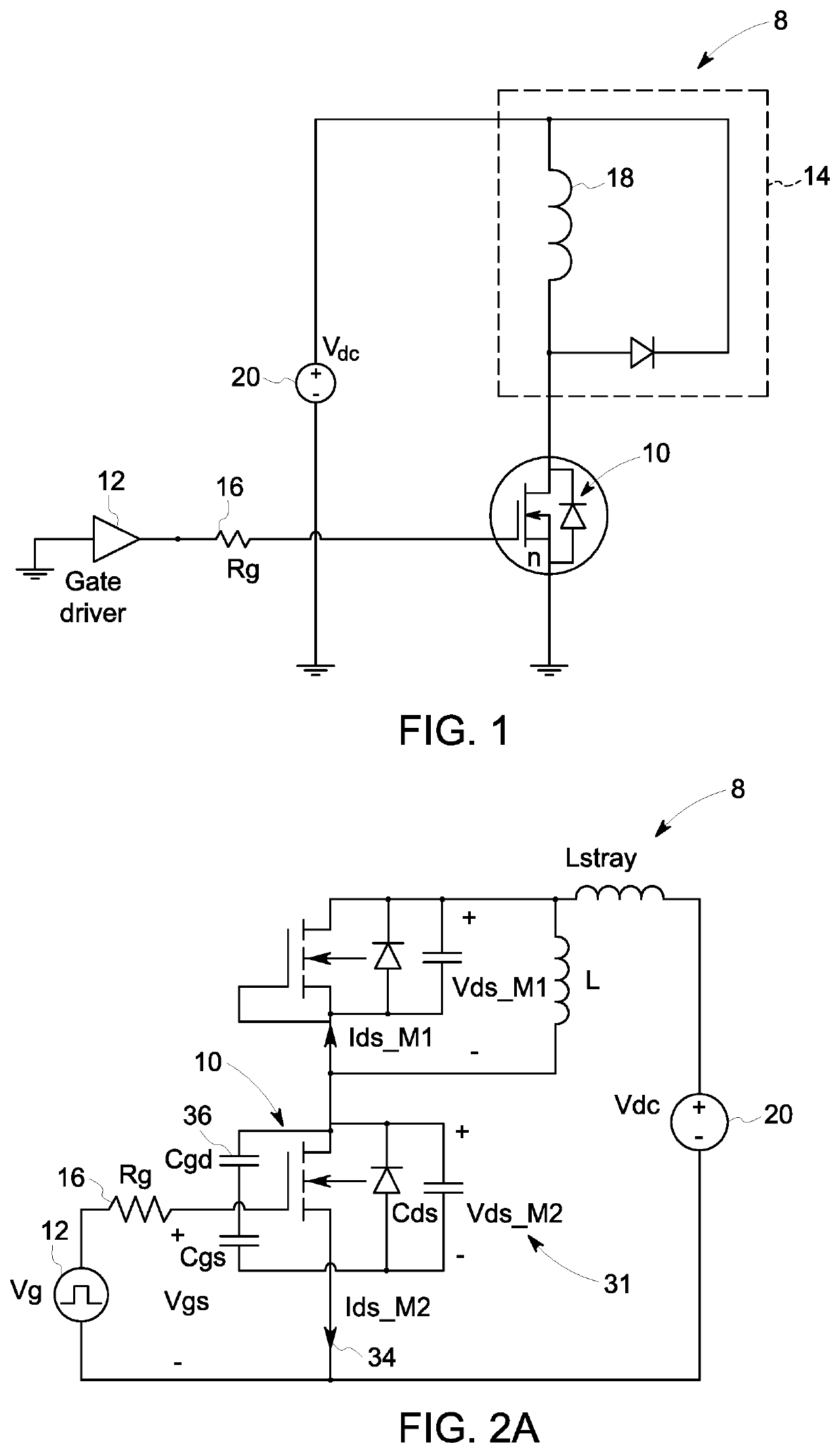
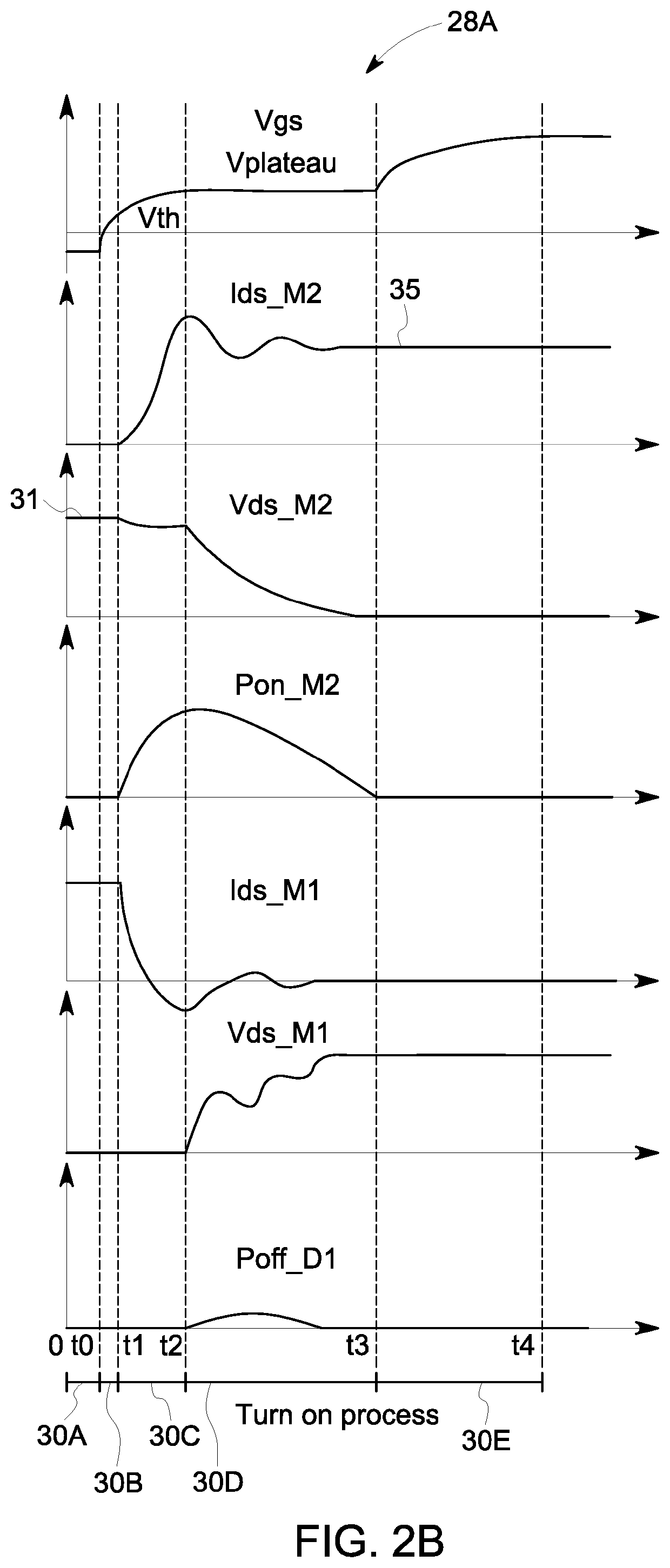
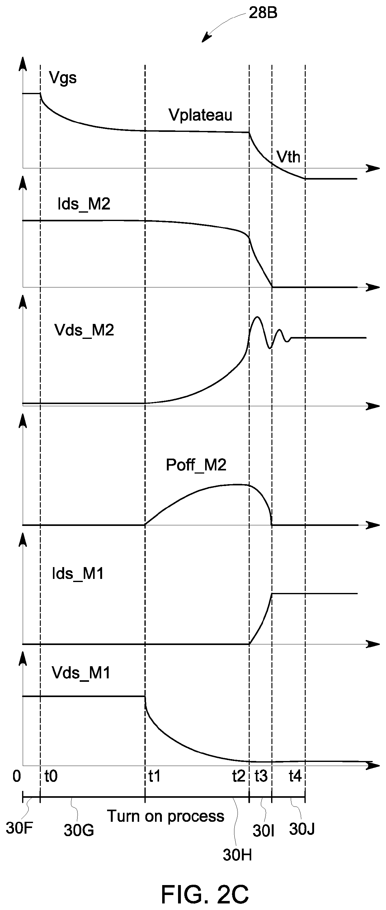
[0005]In one embodiment, a circuit may include a first switching device coupled to a load and a first voltage source that generates an electrical signal at a voltage level at least equal to a threshold voltage of the first switching device. The circuit may also include a second switching device between the first switching device and the first voltage source. The second switching device may provide a shaped current to the first switching device in response to a control signal. The shaped current may be generated based at least in part on the electrical signal generated by the first voltage source. The shaped current actuates the first switching device.
[0006]In another embodiment, a power converter system may include a load that operates based at least in part on a supplied electrical signal. The power converter system also may include a switching network that selectively enables and disables the supplied electrical signal based at least in part on a control scheme associated with operation of the load. The switching network may include a gate driver and a power device. The power device may enable in response to a control signal generated by the gate driver based on the control scheme. Enabling of the power device may selectively

Problems solved by technology

However, power semiconductor device switching is complicated and is difficult to perform quickly since too fast of a turn-on for

Method used


Image

  • Miller transition control gate drive circuit
  • Miller transition control gate drive circuit
  • Miller transition control gate drive circuit

Examples


Example

[0028]One or more specific embodiments of the present embodiments described herein will be described below. In an effort to provide a concise description of these embodiments, all features of an actual implementation may not be described in the specification. It should be appreciated that in the development of any such actual implementation, as in any engineering or design project, numerous implementation-specific decisions must be made to achieve the developers' specific goals, such as compliance with system-related and business-related constraints, which may vary from one implementation to another. Moreover, it should be appreciated that such a development effort might be complex and time consuming, but would nevertheless be a routine undertaking of design, fabrication, and manufacture for those of ordinary skill having the benefit of this disclosure.

[0029]When introducing elements of various embodiments of the present disclosure, the articles “a,”“an,” and “the” are intended to m...


PUM


Abstract

Aspects of the present disclosure are directed toward designs and methods of improving driving of switching devices. One proposed solution to improving driving of switching devices is an auxiliary control circuit that selectively guides the switching device through at least one switching region, permitting an improved operation of the switching device.

Description

TECHNICAL FIELD[0001]The subject matter disclosed herein relates to techniques for improving driving of metal-oxide-semiconductor field-effect transistor (MOSFET) devices and other suitable switching devices.BACKGROUND[0002]This section is intended to introduce the reader to various aspects of art that may be related to various aspects of the present disclosure, which are described and / or claimed below. This discussion is believed to be helpful in providing the reader with background information to facilitate a better understanding of the various aspects of the present disclosure. Accordingly, it should be understood that these statements are to be read in this light, and not as admissions of prior art.[0003]In electronic systems, power semiconductor device, or power semiconductor switching devices, such as MOSFET devices, insulated-gate bipolar transistors (IGBTs), bipolar transistors (BJTs), or the like are leveraged to selectively couple one or more components of the electronic s...

Claims


Application Information

Patent Timeline
IPC IPC(8): H03K17/16H03K17/042H02M1/08
CPCH02M2001/0054H02M1/08H03K17/165H03K17/04206H03K17/166H02M1/0054
Inventor RAMABHADRAN, RAMANUJAMMAINALI, KRISHNAHUH, KUM-KANGHARFMAN-TODOROVIC, MAJATHOMAS, ROBERT JAMESLI, CONG
Owner GENERAL ELECTRIC CO
Why Eureka
Try Eureka