Eureka AIR delivers breakthrough ideas for toughest innovation challenges, trusted by R&D personnel around the world.

Multi-Reflection Mass Spectrometer

Active Publication Date: 2020-07-30
THERMO FISHER SCI BREMEN
View PDF0 Cites 11 Cited by
  • Summary
  • Abstract
  • Description
  • Claims
  • Application Information

AI Technical Summary

Benefits of technology

The patent describes an ion focusing arrangement in a mass spectrometer that uses a combination of injection and reflection to focus ions. An ion deflector is placed before the first reflection in the ion mirrors to adjust the inclination angle of the ion beam. The resulting spatially focused ions make their way to the detector after a designated number of oscillations in the X direction. This results in improved data accuracy and simplified construction of the mass spectrometer.

Problems solved by technology

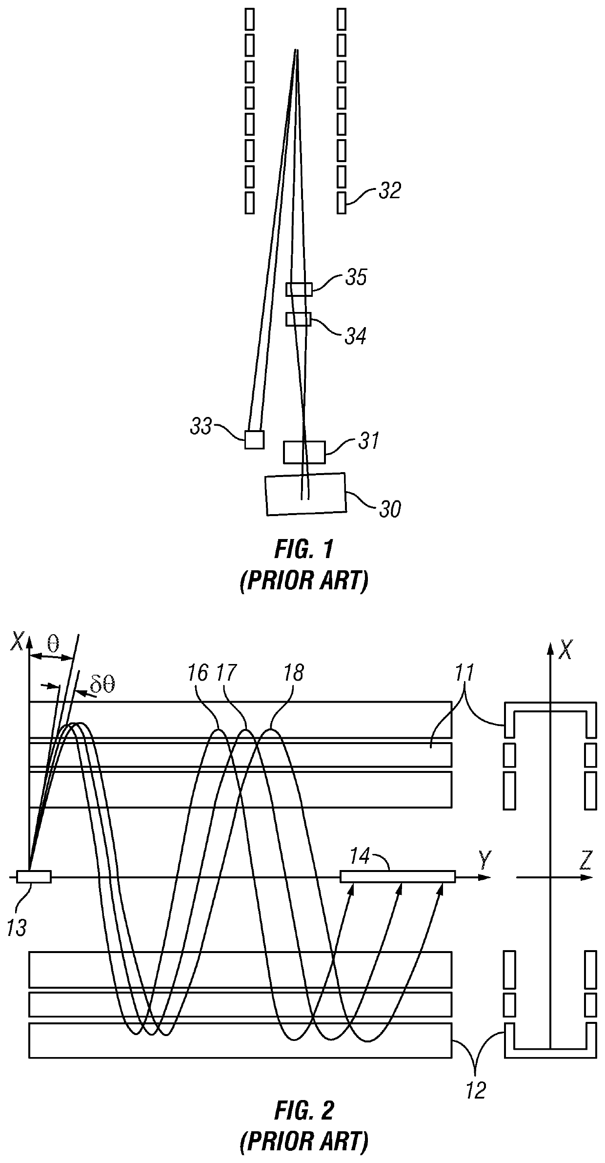
Unfortunately, ion energy distributions and space charge interactions can cause ions to spread out in flight, which in long systems can cause them to be lost from the analyser or to reach the detector at a highly aberrant time-of-flight.
A problem is that the system has no means to reduce ion beam divergence in the drift direction so that only a few reflections are possible until the beam is wider than any detector.
Another problem with an uncontrolled beam expansion is that it can become possible for ions from different numbers of reflections to reach the detector, creating additional “overtone” peaks for ions of a single m / z.
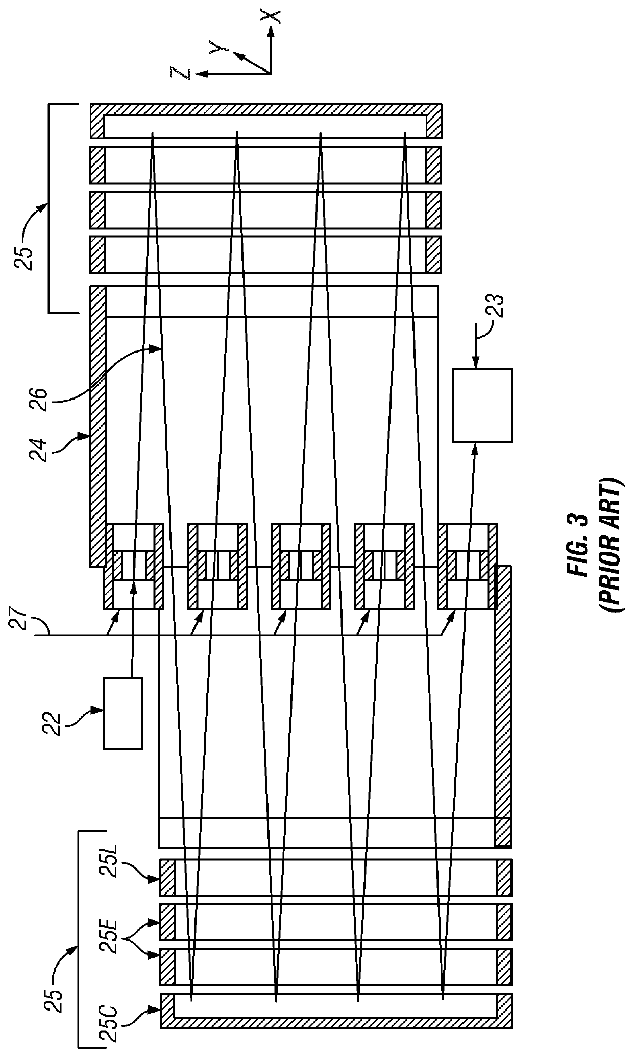
A major downside is that the ion path is strictly defined by the lens position, and requires precise alignment of the many elements to minimise ToF aberrations and ion losses.
The restricted spatial acceptance of the lenses also requires a very tightly focused beam, leaving the system relatively susceptible to space charge effects with higher ion populations.
However, the use of a deflector in this way is prone to introducing beam aberrations which will ultimately limit the maximum resolving power that can be obtained.
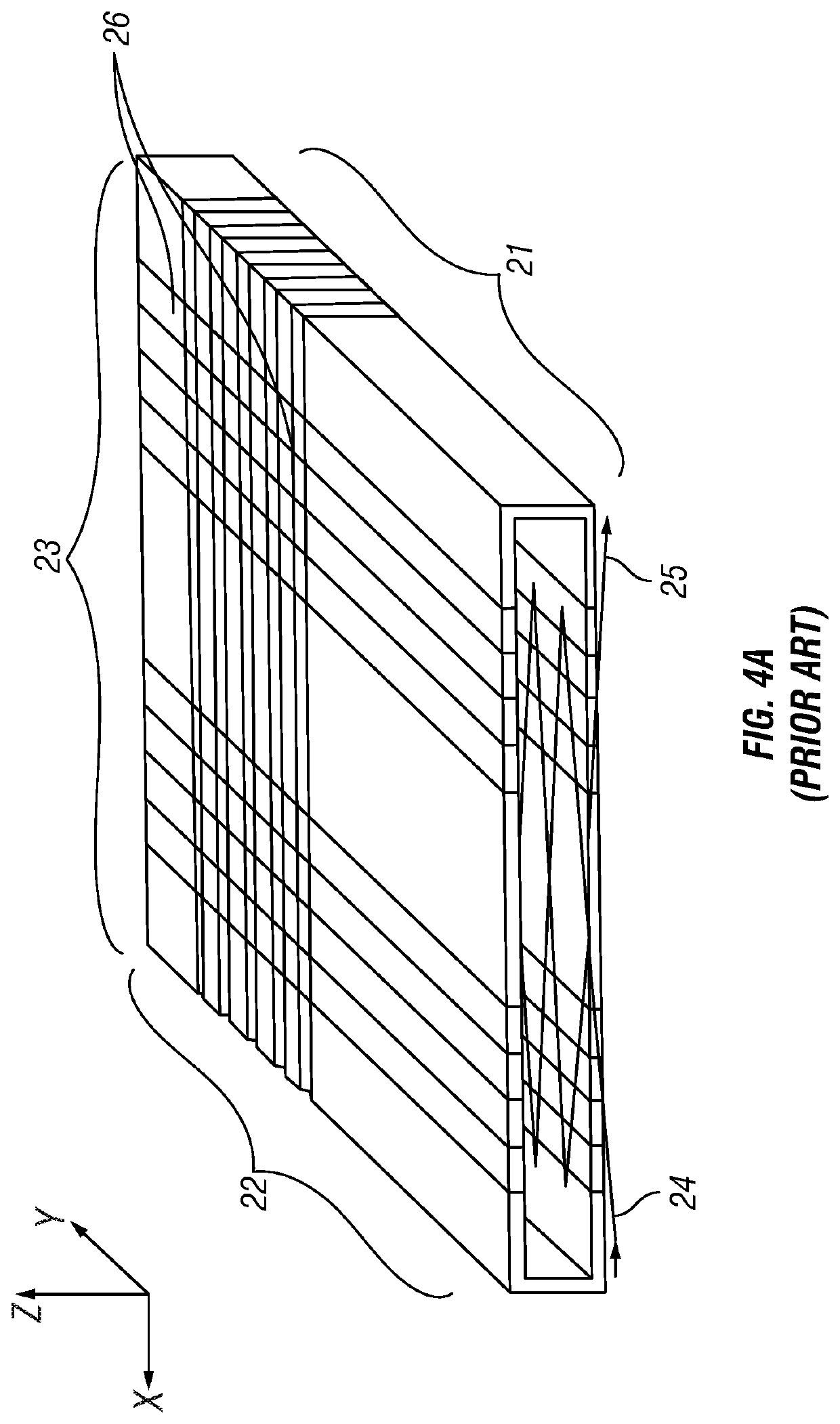
Unfortunately, the strong electric fields between the segments of the opposing mirrors that are required to integrate the third mirror into the electrode structure causes scattering of the ion beam, which is an effect that can only be limited with a high number of segments thereby making mirror construction very complex.

Method used


Image

  • Multi-Reflection Mass Spectrometer
  • Multi-Reflection Mass Spectrometer
  • Multi-Reflection Mass Spectrometer

Examples


Embodiment Construction

[0130]Various embodiments of the invention will now be described with reference to the figures. These embodiments are intended to illustrate features of the invention and are not intended to be limiting on the scope of the invention. It will be appreciated that variations to the embodiments can be made while still falling within the scope of the invention as defined by the claims.

[0131]A multi-reflection mass spectrometer 2 according to an embodiment of the present invention is shown in FIG. 5. Ions generated from an ion source (e.g. ESI or other source), which is not shown, are accumulated in a pulsed ion injector, in this embodiment in the form of ion trap 4. In this case, the ion trap is a linear ion trap, such as a rectilinear ion trap (R-Trap) or a curved linear ion trap (C-trap) for example. An ion beam 5 is formed by extracting a packet of trapped thermalized ions, which has for example less than 0.5 mm width in the drift direction Y, from the linear ion trap 4 and injecting ...


PUM


Abstract

A multi-reflection mass spectrometer comprising two ion mirrors spaced apart and opposing each other in a direction X, each mirror elongated generally along a drift direction Y, the drift direction Y being orthogonal to the direction X, a pulsed ion injector for injecting pulses of ions into the space between the ion mirrors, the ions entering the space at a non-zero inclination angle to the X direction, the ions thereby forming an ion beam that follows a zigzag ion path having N reflections between the ion mirrors in the direction X whilst drifting along the drift direction Y, a detector for detecting ions after completing the same number N of reflections between the ion mirrors, and an ion focusing arrangement at least partly located between the opposing ion mirrors and configured to provide focusing of the ion beam in the drift direction Y, such that a spatial spread of the ion beam in the drift direction Y passes through a single minimum at or immediately after a reflection having a number between 0.25N and 0.75N, wherein all detected ions are detected after completing the same number N of reflections between the ion mirrors.

Description

CROSS-REFERENCE TO RELATED APPLICATIONS[0001]This application claims the priority to GB Patent Application No. 1820950.2, filed on Dec. 21, 2018, which application is hereby incorporated herein by reference in its entirety.FIELD OF THE INVENTION[0002]This invention relates to the field of mass spectrometry, in particular time-of-flight mass spectrometry and electrostatic trap mass spectrometry. The invention especially relates to time-of-flight mass spectrometry and electrostatic trap mass spectrometry utilizing multi-reflection techniques for extending the ion flight path and increasing mass resolution.BACKGROUND[0003]Time of flight (ToF) mass spectrometers are widely used to determine the mass to charge ratio (m / z) of ions on the basis of their flight time along a flight path. In ToF mass spectrometry, short ion pulses are generated by a pulsed ion injector and directed along a prescribed flight path through an evacuated space to reach an ion detector. The detector then detects th...

Claims


Application Information

Patent Timeline
IPC IPC(8): H01J49/40H01J49/06
CPCH01J49/406H01J49/004H01J49/061H01J49/405H01J49/282H01J49/025H01J49/06H01J49/067H01J49/0031H01J49/4245
Inventor STEWART, HAMISHGRINFELD, DMITRY E.MAKAROV, ALEXANDER A.
Owner THERMO FISHER SCI BREMEN
Why Eureka
Eureka Blog
Learn More