Optical satellite communication

Active Publication Date: 2020-07-30
NEDERLANDSE ORG VOOR TOEGEPAST-NATUURWETENSCHAPPELIJK ONDERZOEK (TNO)
View PDF0 Cites 0 Cited by
  • Summary
  • Abstract
  • Description
  • Claims
  • Application Information

AI Technical Summary

Benefits of technology

This patent describes a method of improving the quality of communication by using a separate guidance star satellite to create a reference beam for wavefront correction. By traveling through the same part of the atmosphere, the wavefront distortion in the reference beam can be better correlated with the distortion experienced by the uplink beam. This pre-correction can remove distortion caused by the atmosphere. By having the guidance star satellite travel in the same orbit, direction, and velocity as the communication satellite, the distance between them can be fixed to allow better continuous communication. Additionally, the use of a guidance star satellite with mirror or other directional optics can allow for the efficient and reliable redirecting of light from a celestial object, such as the sun or moon, for use as the reference beam.

Problems solved by technology

However, atmospheric turbulence can distort the laser beam which may cause reduced detected laser power and even induce bit errors.
However, no application for improving communication is envisaged, only imaging space and debris.
However, resolving an image of the satellite does not improve communication, particularly uplink communication.
In the transmittal, the beam travels through an atmosphere there between, which may cause a distortion of its wavefront.

Method used


Image

  • Optical satellite communication
  • Optical satellite communication
  • Optical satellite communication

Examples


Embodiment Construction

[0013]Terminology used for describing particular embodiments is not intended to be limiting of the invention. As used herein, the singular forms “a”, “an” and “the” are intended to include the plural forms as well, unless the context clearly indicates otherwise. The term “and / or” includes any and all combinations of one or more of the associated listed items. It will be understood that the terms “comprises” and / or “comprising” specify the presence of stated features but do not preclude the presence or addition of one or more other features. It will be further understood that when a particular step of a method is referred to as subsequent to another step, it can directly follow said other step or one or more intermediate steps may be carried out before carrying out the particular step, unless specified otherwise. Likewise it will be understood that when a connection between structures or components is described, this connection may be established directly or through intermediate stru...


PUM


Abstract

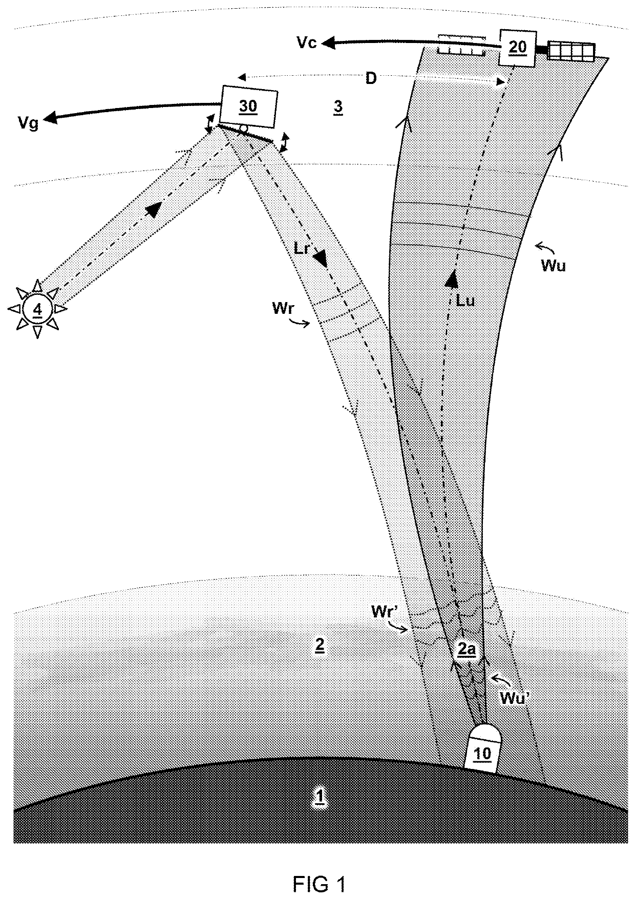
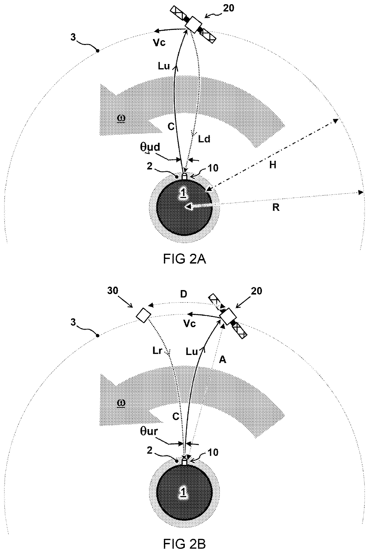
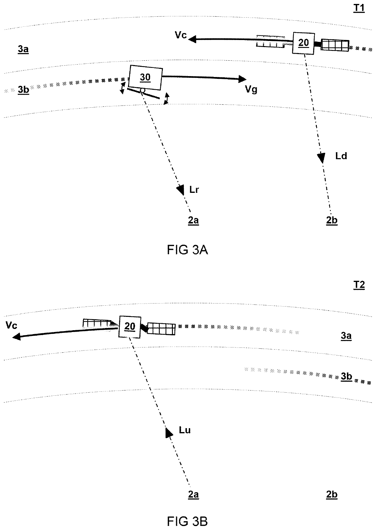
Information encoded in an uplink beam (Lu) is transmitted from transceiver (10) on earth (1) to a communication satellite (20) in orbit. The uplink beam (Lu) travels through an atmosphere (2) there between, wherein a wavefront (Wu) of the uplink beam (Lu) is distorted as a result of its propagation through the atmosphere (2). The transceiver (10) comprises a wavefront sensor (12) to measure a reference distortion (Wr′) of a wavefront (Wr) of a reference beam (Lr). Adaptive optics (11) are used to pre-correct a wavefront (Wu) of the uplink beam (Lu) prior to its transmission based on the measured reference distortion (Wr′). The reference beam (Lr) originates from a guidestar satellite (30) formed by a separate man-made object at a distance (D) from the communication satellite (20) such that the reference beam (Lr) travels through the same part (2a) of the atmosphere (2) as the uplink beam (Lu).

Description

TECHNICAL FIELD AND BACKGROUND[0001]The present disclosure relates to optical communication between the ground and a satellite in orbit above the earth.[0002]Optical laser communication can increase data rate from transceivers to satellites compared to radio waves. For example, an optical laser beam may carry higher frequencies for communication and can be focused to a specific target. However, atmospheric turbulence can distort the laser beam which may cause reduced detected laser power and even induce bit errors. In some instances, adaptive optics can be used to mitigate atmospheric turbulence. For example, an adaptive optics system can have a wavefront sensor which measures the distortion effects caused by atmospheric turbulence. In order to do so, typically a reference beam is needed which goes through the atmosphere. For example, the down-link laser beam, which is used for communication from the satellite to the transceiver, can be used as reference. However, because the earth ...

Claims


Application Information

Patent Timeline
IPC IPC(8): H04B10/118
CPCH04B10/118H04B10/40H04B10/60H04B10/43H04B10/50
Inventor SAATHOF, RUDOLF
Owner NEDERLANDSE ORG VOOR TOEGEPAST-NATUURWETENSCHAPPELIJK ONDERZOEK (TNO)
Why Eureka
Try Eureka