A method of recovering phenol in a melt polycarbonate polymerization

a polycarbonate polymerization and phenol technology, applied in the field of recovering phenol in a melt polycarbonate polymerization, can solve the problems of high operational and capital cost, and the design of such condensers that can withstand the thermal stresses caused by switching utilities, and achieve the effect of increasing both capital and operating costs

Inactive Publication Date: 2020-08-13
SABIC GLOBAL TECH BV
View PDF0 Cites 0 Cited by
  • Summary
  • Abstract
  • Description
  • Claims
  • Application Information

AI Technical Summary

Benefits of technology

[0004]Another method for recovering phenol from the overhead streams during a melt polycarbonate polymerization utilizes a liquid scrubbing solution of phenol and a liquid freezing-point depressant to prevent solidification of the recovered phenol from the polymerization units. An example of such a method is illustrated in FIG. 2 that illustrates overhead stream 12 being removed from polymerization unit 10 and directed towards wet scrubber 30. Liquid scrubbing solution 32 is sprayed into a top portion of wet scrubber 30 so that liquid scrubbing solution 32 makes contact with the phenol vapor, condensing the vapor and absorbing it into the liquid scrubbing solution. Even though, from a thermodynamic stand point, it is feasible to use a wet scrubber, from an applicability stand point there are significant challenges to using such a scrubber in industrial settings. For example, the scrubbing solution must be recovered and recycled, increasing both the capital and operating costs. Furthermore, this method of recovering the phenol from the overhead streams requires an extremely low pressure drop of less than 0.5 millibar and such a low pressure drop can lead to difficulty in maintaining the required vacuum levels in the polymerization units.

Problems solved by technology

As the utility between the two condensers is constantly being switched from chilled water to steam depending on the operation mode, the design of such condensers that can withstand the thermal stresses caused by switching of utility is extremely challenging.
In summary, fouling, interrupted cyclic operations, and exotic valve design make the overhead processing of melt polymerization units expensive both from an operational stand point as well as from the perspective of capital cost.
Even though, from a thermodynamic stand point, it is feasible to use a wet scrubber, from an applicability stand point there are significant challenges to using such a scrubber in industrial settings.
For example, the scrubbing solution must be recovered and recycled, increasing both the capital and operating costs.
Furthermore, this method of recovering the phenol from the overhead streams requires an extremely low pressure drop of less than 0.5 millibar and such a low pressure drop can lead to difficulty in maintaining the required vacuum levels in the polymerization units.
This approach though has several limitations as the effective distribution of the inert gas in the polymerization mixture at a large scale in individual, industrial polymerization units is difficult, where a high vapor velocity in the unit results in issues such as foaming, entrainment of oligomers and polymer, and / or clogging of scrubbers and vacuum units.
These problems are exacerbated by the presence of the multiple oligomerization and polymerization units present in a polymerization facility that each produce an overhead stream comprising the phenol by-product.
In practice, the economics would be expensive to have a dedicated scrubber for every polymerization unit and a common scrubber for multiple reactors would take away the degree of freedom to control reactor pressures.

Method used


Image

  • A method of recovering phenol in a melt polycarbonate polymerization
  • A method of recovering phenol in a melt polycarbonate polymerization
  • A method of recovering phenol in a melt polycarbonate polymerization

Examples


examples 1-2

Continuous Condensation of a Phenol Solvent Mixture

[0054]A lab scale distillation column was set up where a single-neck round-bottom flask was heated using an oil bath. A jacketed distillation column was attached to the neck of the round-bottom flask and cooling water was flowed in the jacket of the distillation entering from a lower inlet and exiting from an upper outlet. A vacuum pump was hooked up to the top of the distillation column to control the pressure in the column.

[0055]In Example 1 a solution comprising 6 volume percent (vol %) of phenol and 33.4 vol % of diphenyl carbonate was added to the round-bottom flask. A temperature of the entering cooling water was 30° C. and the pressure was set to 1.5 millibar. Severe freezing was observed in the distillation column as soon as it started boiling.

[0056]In Example 2, a solution comprising 30.1 vol % of phenol, 15.1 vol % of diphenyl carbonate, and 54.8 vol % phenyl methyl carbonate was added to the round-bottom flask. A temperat...

example 3-5

Effect of Solvent Presence in the Separation Column

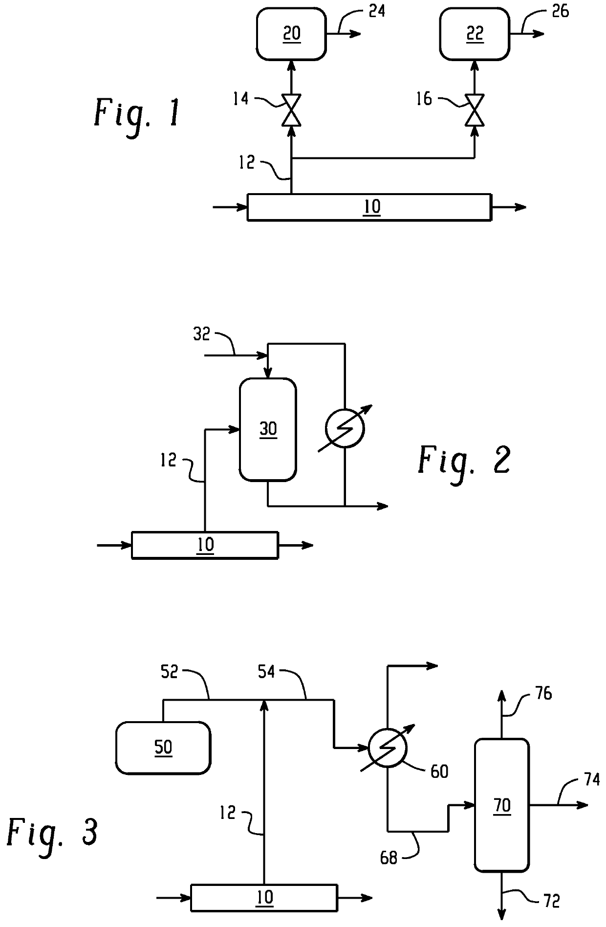
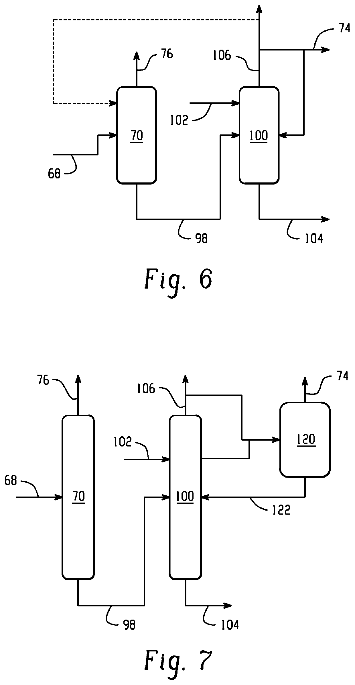
[0057]In Example 3, a simulation using ASPEN software was performed using separation column 70 as illustrated in FIG. 6 using a feed location in between the middle packing section and the lower packing section and instead using the feed stream that was freeze condensed stream 24 as illustrated in FIG. 1. The results are shown in Table 1, where the total mass flow rate is shown in kilograms per hour (kg / hr).

TABLE 1PhenolFeedBottomrecoveryStreamstreamstreamstreamStream number249876Total mass flow rate (kg / hr)2,5008001,700Phenol (wt %)695100Diphenyl carbonate (wt %)2888—Bisphenol A (wt %)25—Other (wt %)12—Pressure (bar absolute)10.150.07Temperature (° C.)135190107

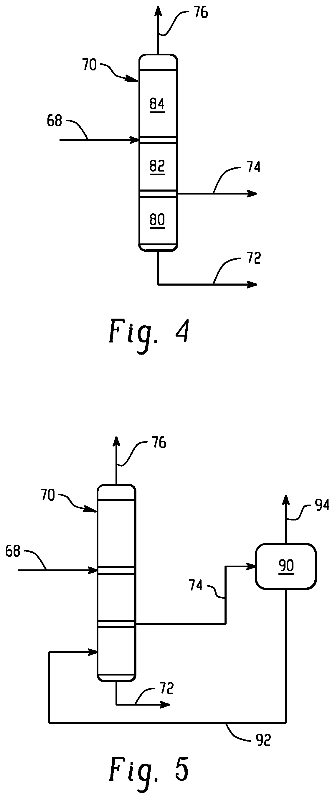
[0058]In Example 4, a simulation using ASPEN software was performed using separation column 70 as illustrated in FIG. 4. The results are shown in Table 2.

TABLE 2DiphenylcarbonateSolventPhenolFeedrecoveryrecoveryrecoveryStreamstreamstreamstreamstreamStream number68727476Total m...


PUM

PropertyMeasurementUnit
vapor pressureaaaaaaaaaa
freezing pointaaaaaaaaaa

Abstract

In an embodiment, a method of manufacture of a melt polycarbonate comprises melt polymerizing a bisphenol and diphenyl carbonate to form phenol and the melt polycarbonate in a polymerization unit; removing an overhead stream comprising the phenol in a gas phase from the polymerization unit; combining the overhead stream with a gas stream comprising a solvent in a gas phase to form a combined gas stream; wherein the combined gas stream has a freezing point at less than 3 mbar absolute that is less than the triple point of phenol; and condensing the combined gas stream in a condenser to form a condensed stream comprising the phenol and the solvent in a liquid phase.

Description

CROSS-REFERENCE TO RELATED APPLICATION[0001]This application claims the benefit of European Patent Application Serial No. 17382596 filed September 6, 2017. The related application is incorporated herein in its entirety by reference.BACKGROUND[0002]During the melt polymerization of bisphenol A (BPA) polycarbonate, the polymerization occurs in polymerization units that operate at high vacuum levels of up to 0.5 millibar in order to remove a reaction vapor comprising the phenol by-product, driving polymerization. The phenol by-product is in the solid phase as the pressure in the polymerization units is below the triple point of the phenol and also due to the presence of diphenyl carbonate (up to 60% weight by weight) that further increases the freezing point of the removed vapor. Therefore, in order to recover the phenol from the removed vapor, the industry today generally employs a minimum of two freeze condensers per polymerization unit that operate alternatively, where one of the co...

Claims


Application Information

Patent Timeline
Patent Type & Authority Applications(United States)
IPC IPC(8): C08G64/30
CPCC08G64/307C07C37/52Y02P20/10C07C39/04
Inventor IMAM, RAYEES AHAMEDGUNALE, TUKARAMANAPAT, SAMIRMATEOS SALVADOR, FERNAN
Owner SABIC GLOBAL TECH BV
Why Eureka
Try Eureka