Tool Holder For Ultrasonic Machining

a tool holder and ultrasonic technology, applied in the field of tool holders, can solve the problems of affecting the precision of the workpiece, adversely affecting the high frequency vibration, and the workpiece may be very low, and achieve the effect of improving the smoothness and quality of the workpi

Inactive Publication Date: 2020-09-03
XPOLE PRECISION TOOLS
View PDF0 Cites 0 Cited by
  • Summary
  • Abstract
  • Description
  • Claims
  • Application Information

AI Technical Summary

Benefits of technology

[0007]It is therefore one object of the invention to provide a tool holder for ultrasonic machining wherein an oscillator for producing ultrasonic vibration is disposed in the tool mounting member so that the path for transmitting the vibration of high frequency can be greatly decreased, undesired vibration to the tool holder by the high frequency vibration can be eliminated, and smoothness and quality of the workpiece are improved.

Problems solved by technology

However, components may collide one another resulting in undesired vibration which may interfere with the high frequency vibration.
An in turn, it may adversely affect precision of the workpiece.
For high length to diameter (L / D) ratio, the precision of the workpiece may be very low or even be impossible of being machined due to rigidity of the material of the tool holder.
These are problems encountered by the conventional ultrasonic machines.
Further, in USM the path of transmitting vibration may be very long.
And in turn, it may cause strong interference to undesirably vibrate the tool holder.
Furthermore, the maximum amplitude of the vibration frequencies cannot be controlled to focus on the tip of the tool.
And in turn, the cutting effect is adversely affected.
Also, smoothness and quality of the workpiece are low.
To the worse, the ultrasonic machines are damaged.

Method used


Image

  • Tool Holder For Ultrasonic Machining
  • Tool Holder For Ultrasonic Machining
  • Tool Holder For Ultrasonic Machining

Examples


Embodiment Construction

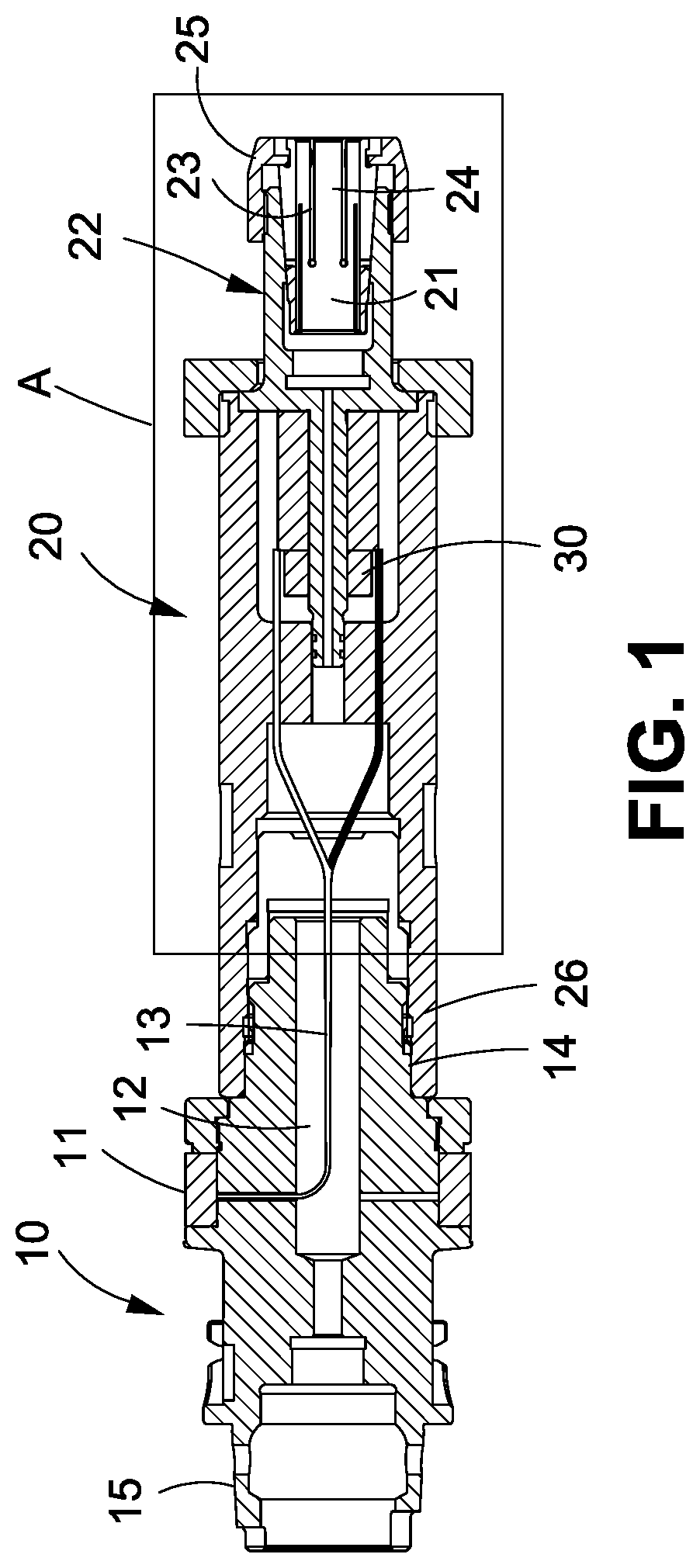
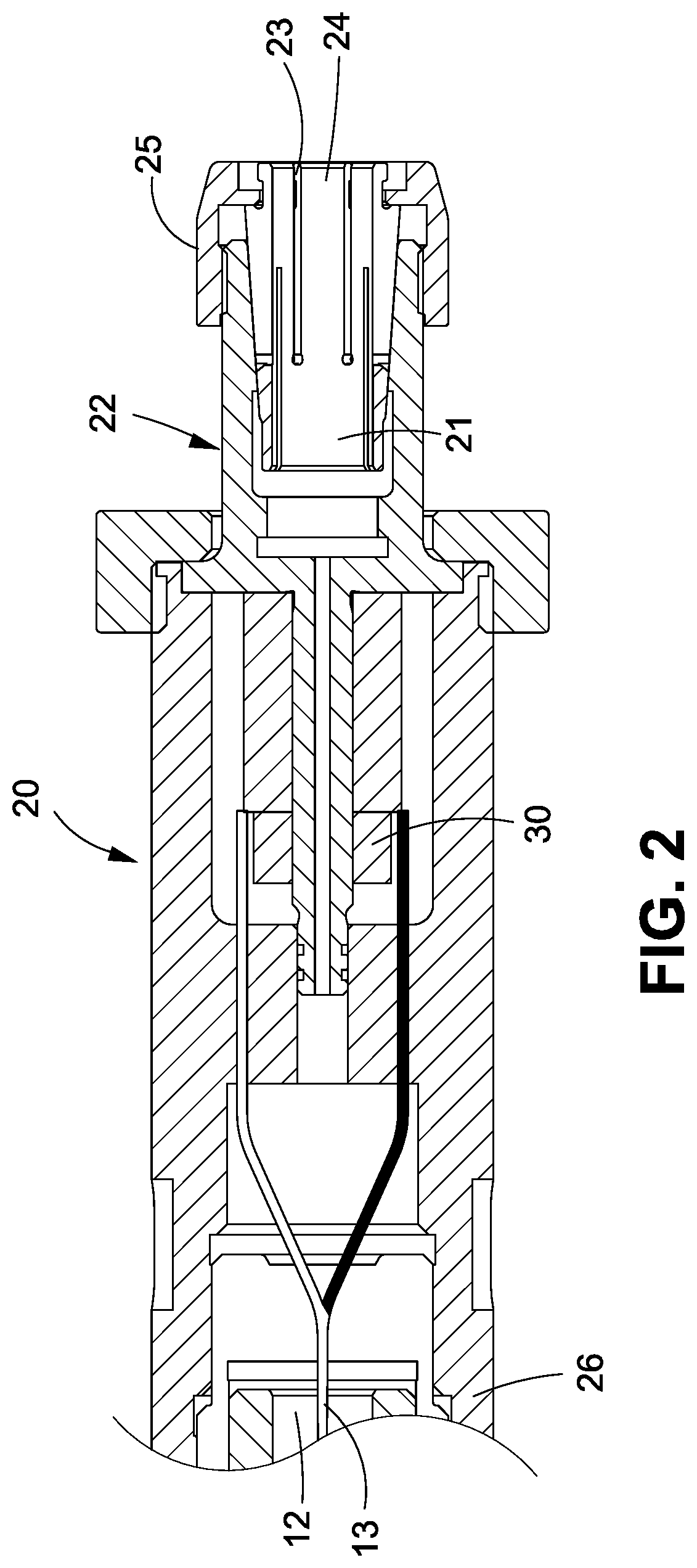
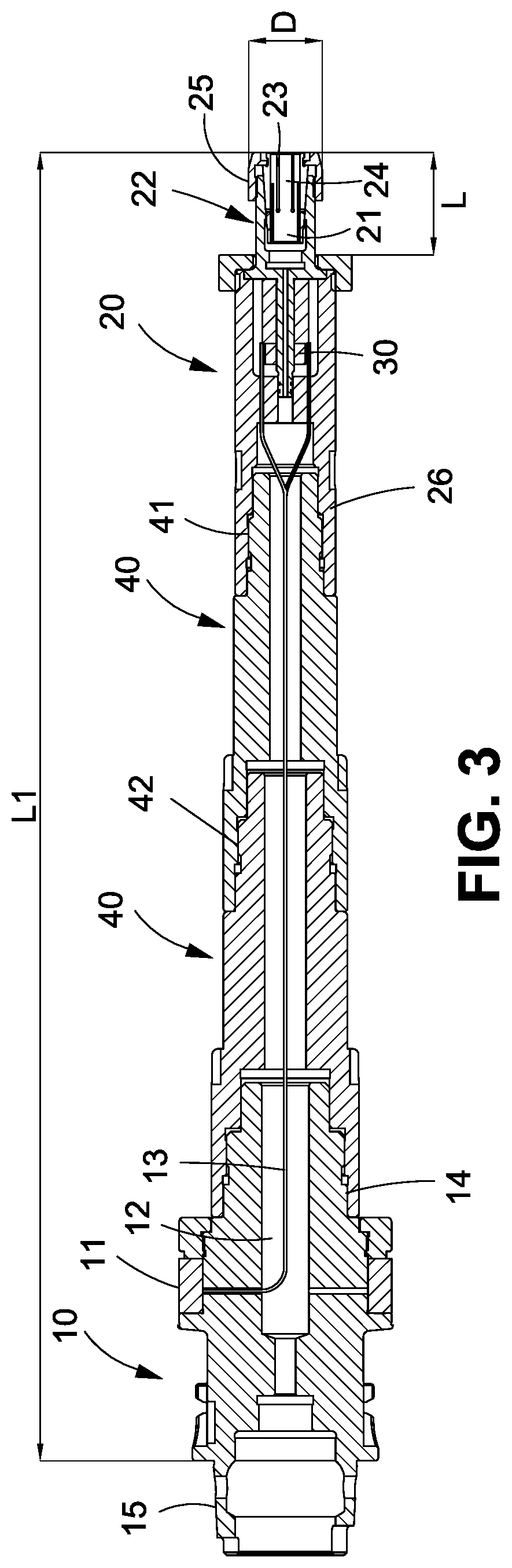
[0019]Referring to FIGS. 1 and 2, a tool holder for ultrasonic machining according to a first preferred embodiment of the invention is used in a machine which supplies power via a spindle (not shown). The tool holder for ultrasonic machining comprises a connector 10 received in the spindle, a conductive ring 11 disposed on the connector 10 and electrically connected to the spindle so that power may be supplied to the tool holder; a tool mounting member 20 including an axial hole 21 for fastening a portion of a tool (e.g., tool handle but not shown); and an oscillator 30 for producing ultrasonic vibration disposed in the tool mounting member 20, the oscillator 30 for producing ultrasonic vibration electrically connected to the conductive ring 11 so that power may be supplied to the oscillator 30 for producing ultrasonic vibration. The produced vibration of high frequency is transmitted to the tool via the axial hole 21. As a result, the path for transmitting the vibration of high fre...


PUM

PropertyMeasurementUnit
poweraaaaaaaaaa
frequencyaaaaaaaaaa
forceaaaaaaaaaa

Abstract

A tool holder for ultrasonic machining used in a machine which supplies power via a spindle is provided with a connector received in the spindle; a conductive ring disposed on the connector and electrically connected to the spindle so as that power is configured to supply to the tool holder; a tool mounting member including an axial hole for fastening a portion of a tool; and an oscillator for producing ultrasonic vibration disposed in the tool mounting member, the oscillator for producing ultrasonic vibration electrically connected to the conductive ring so that power supplied to the oscillator for producing ultrasonic vibration is configured to produce ultrasonic vibration of high frequency. The produced ultrasonic vibration of high frequency is transmitted to the tool via the axial hole.

Description

BACKGROUND OF THE INVENTION1. Field of the Invention[0001]The invention relates to relates to tool holders and more particularly to a tool holder for ultrasonic machining.2. Description of Related Art[0002]Conventional ultrasonic machining (USM) involves mounting an electronic oscillator on a spindle. The oscillator produces an alternating current oscillating at a high frequency in the ultrasonic range. A transducer converts the oscillating current to a mechanical vibration which is transmitted to a tool held by a holder. USM can remove material from the surface of a part through high frequency, low amplitude vibrations of the tool against the material surface in the presence of fine abrasive particles. USM is typically used on brittle materials as well as materials with a high hardness due to the microcracking mechanics.[0003]The tool travels vertically or orthogonal to the surface of the part. The fine abrasive grains are mixed with water to form slurry that is distributed across ...

Claims


Application Information

Patent Timeline
Patent Type & Authority Applications(United States)
IPC IPC(8): B23B31/26
CPCB23B31/26B23B2231/42B23B31/02B23B37/00B23B2270/10B23B2231/04B23B31/2025B23B2231/56
Inventor CHEN, PETER
Owner XPOLE PRECISION TOOLS
Why Eureka
Try Eureka