Compact LNG production train and method

a production train and compact technology, applied in the direction of lighting and heating equipment, industrial buildings, solidification, etc., can solve the problems of large overall footprint of modularized lng production plants, large capital expenditure, and compromises in the placement of module boundaries, so as to achieve the effect of relatively small footprint of each process uni

Inactive Publication Date: 2020-10-01
SHELL OIL CO
View PDF2 Cites 8 Cited by
  • Summary
  • Abstract
  • Description
  • Claims
  • Application Information

AI Technical Summary

Benefits of technology

[0013]In one aspect, the present invention is directed to a liquefied natural gas production train, comprising at least one integrated process unit having a structural frame forming multiple process equipment floors. The multiple process equipment floors enable respective process equipment to be arranged vertically offset with respect to each other, allowing the footprint of each process unit to be relatively small.
[0014]In an embodiment, the at least one integrated process unit extends in vertical direction, wherein a height of the at least one integrated process unit is substantially equal to or larger than a width and a length of the at least one integrated process unit. The vertically built integrated process units extend in vertical direction, limiting the footprint. Limited footprint allows limiting capital expenditure, for instance by limiting construction schedule overruns.
[0016]In an embodiment, the structural frame of one or more of the at least one integrated process units being arranged on supports, the supports lifting a lower process floor a predetermined distance above ground. Lifting the lower process floor above ground level allows gravity draining of process sections. It also allows to limit required drainage points, as subsequent pieces of process equipment in a process section may all drain to the same drainage location. Drainage points may be shared with larger process equipment, such as cryogenic heat exchangers or compressors, which may be located at ground level. A limited number of drainage points at ground level is safer and may speed up restarting the liquefaction train after a shutdown. The predetermined distance may be in the order of 1 to 5 meters.

Problems solved by technology

Until now, modularization has been conducted by slicing up an existing stick built LNG train design into transportable sections, leading to some compromises regarding the placement of the module boundaries.
The overall footprint of such modularized LNG production plants is large because sufficient plot space needs to be allocated to allow for covered modules incorporating the air-cooled heat exchanger bank to be positioned in a straight line running along the central longitudinal axis of the LNG production train with the uncovered modules being offset from the central longitudinal axis and located on one side or the other side of the centrally located air-cooled heat exchanger bank.
These prior art designs rely on duplication of structural steel as there is inevitably a large amount of void space underneath the air-cooled heat exchanger bank in addition to the structural steel that is used for the uncovered spatially offset process equipment modules.
Also, capital expenditure is still relatively high.
In addition, many LNG facilities are planned to be built in, or have been built in countries having relatively high labor costs.
Modularization, which for instance aimed to circumvent high labor costs by constructing (modules of) facilities in a location having reduced costs of labor and subsequently move the preconstructed modules to the LNG production location, has disappointed in practice, i.e. production costs remained relatively high compared to older facilities.
LNG production trains typically have a significant impact on capital expenditure and plot space of an LNG production plant.

Method used


Image

  • Compact LNG production train and method
  • Compact LNG production train and method
  • Compact LNG production train and method

Examples


Embodiment Construction

[0052]Certain terms used herein are defined as follows:

[0053]The term “LNG” refers to liquefied natural gas.

[0054]The term “plant” may refer to the LNG production plant including one or more LNG production trains.

[0055]The term “facility” may typically refer to an LNG production plant, but may alternatively refer to an assembly in general.

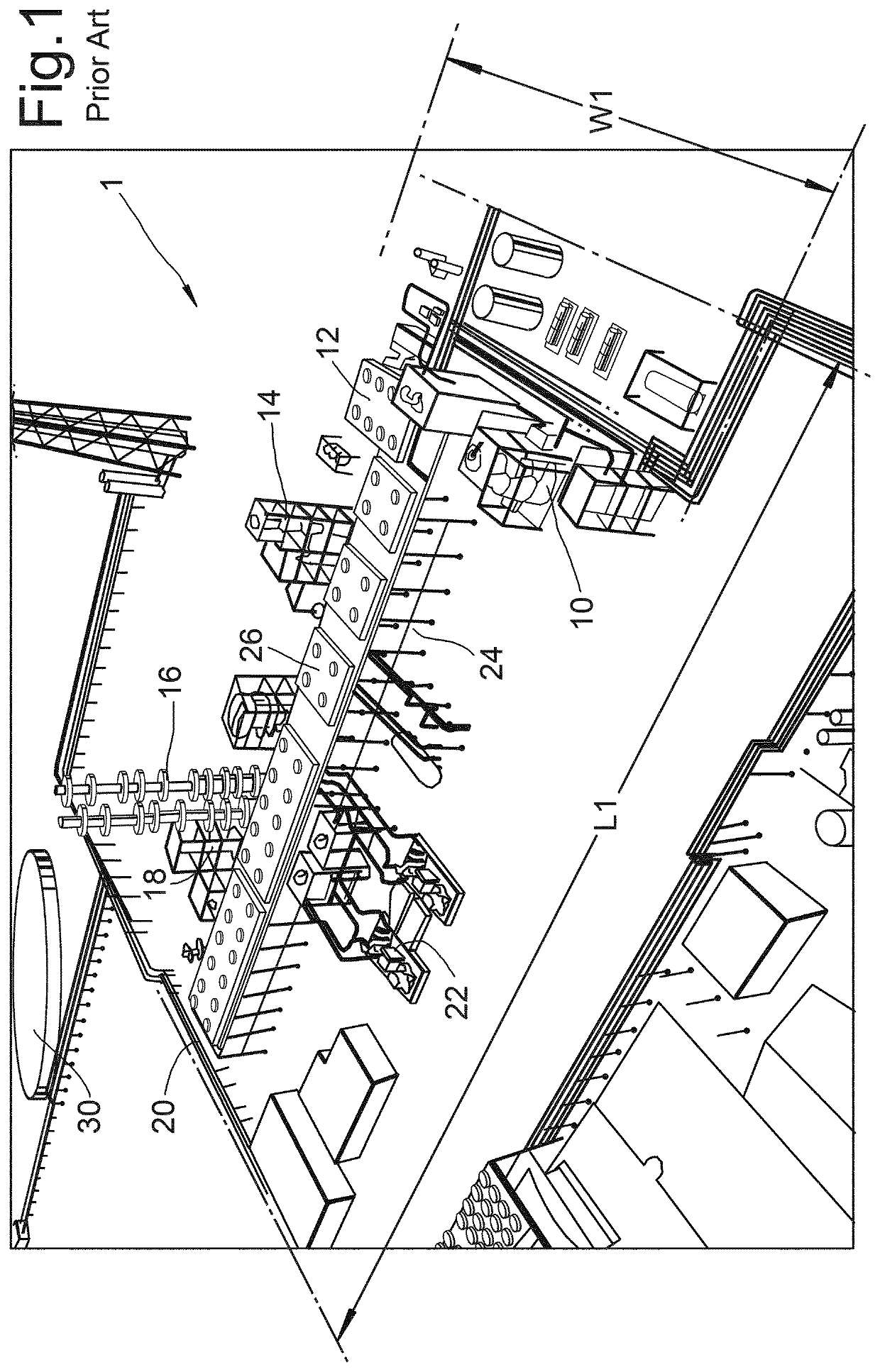
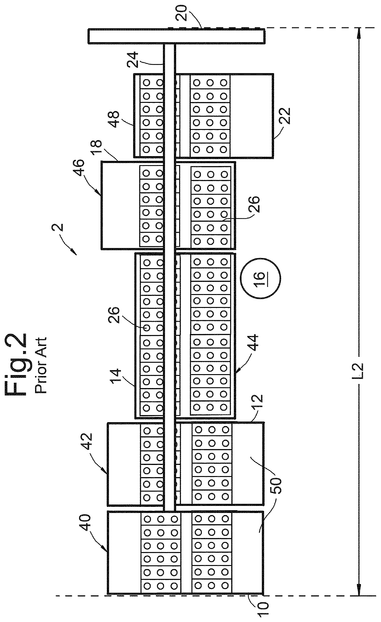
[0056]The term “LNG production train” refers to an assembly comprising process units used for the pre-treatment of a natural gas feed stream to remove contaminants and provided treated gas, and process units used for receiving the treated gas and subjecting the treated gas to cooling to form liquefied natural gas.

[0057]The term “stick-built” refers to an LNG production train which has sections built in subsequent order at the production location. Herein, stick-built is similar to conventional construction. Both refer to construction of a production train or another section of a plant predominantly at a production location. Herein, production locati...


PUM


Abstract

Disclosed is a liquefied natural gas production train, comprising at least one integrated process unit having a structural frame forming multiple process equipment floors. The at least one integrated process unit extends in vertical direction, wherein a height of the at least one integrated process unit is substantially equal to or larger than a width and a length of the at least one integrated process unit. The disclosure also provides a method of producing liquefied natural gas, using the LNG production train.

Description

FIELD OF THE INVENTION[0001]The present invention is directed to a liquefied natural gas production train and a method for the production of liquefied natural gas (LNG).BACKGROUND TO THE INVENTION[0002]Natural gas (“NG”) is routinely transported from one location to another location in its liquid state as “Liquefied Natural Gas” (LNG). Liquefaction of the natural gas makes it more economical to transport as LNG occupies only about 1 / 600 of the volume that the same amount of natural gas does in its gaseous state. After liquefaction, LNG is typically stored in cryogenic containers, typically either at or slightly above atmospheric pressure. LNG can be regasified before distribution to end users through a pipeline or other distribution network at a temperature and pressure that meets the delivery requirements of the end users.[0003]Wellhead gas is subjected to gas pre-treatment to remove contaminants prior to liquefaction. The hydrogen sulphide and carbon dioxide can be removed using a...

Claims


Application Information

Patent Timeline
Patent Type & Authority Applications(United States)
IPC IPC(8): F25J1/00
CPCF25J1/0292F25J1/0052F25J1/0022F28F2280/00F25J1/0283F25J2210/60F25J2245/02E04H5/02F25J1/0216F25J1/0244F25J1/0247F25J1/0248F25J1/0256F25J1/0259F25J1/0269F25J1/0278F25J1/0296F25J1/0055F25J1/0087F25J1/0258F25J2220/64F25J2290/42
Inventor MORLEY, PHILIP WILLIAMKUIVENHOVEN, ANDRIES
Owner SHELL OIL CO
Why Eureka
Try Eureka