Fabric for airbag, coated fabric for airbag, and airbag using same

a technology for airbags and fabrics, applied in the direction of pedestrian/occupant safety arrangements, vehicular safety arrangements, physical treatment, etc., can solve the problems of increasing damage per multifilament yarn, reducing the tensile strength of airbag fabric, and pyro-type inflators tend to significantly damage the fabric used for airbags, etc., to achieve stable airbag deployment and mitigate seam damage

Active Publication Date: 2020-11-12
TOYOBO CO LTD
View PDF0 Cites 0 Cited by
  • Summary
  • Abstract
  • Description
  • Claims
  • Application Information

AI Technical Summary

Benefits of technology

[0016]The present invention provides an airbag fabric and a coated fabric for airbags that are lightweight and compact during packing; that have the tensile strength required when the airbag deploys; that can mitigate damage to seams, as compared with conventional fabrics; and that allow for stable airbag deployment.

Problems solved by technology

Therefore, due to hot air, pyro-type inflators tend to significantly damage the fabric used for airbags.
In particular, in airbags formed by cutting and sewing, high-temperature gas concentratedly released through holes at seams may melt the holes, and adjacent holes may be connected to each other to problematically form stitch-merging.
If the total fineness of the multifilament yarn used is made thinner or the weave density of fabric used for airbags is lowered to achieve light weight and compactness of airbag fabric so as to meet the above need for development, a problem arises such that when hot air passes through holes at seams, damage per multifilament yarn increases due to a reduced heat capacity per multifilament yarn.
Further, if the total fineness of the multifilament yarn used is made thinner or the weave density of fabric used for airbags is lowered, light weight and compactness are improved; however, tensile strength of the airbag fabric is reduced, and thus the mechanical properties required for airbags to restrain occupants cannot be provided.
However, there has been nothing developed thus far that is problem-free.
However, PTL 1 does not verify the relationship between thermal stress characteristics and damage to seams.
Furthermore, when original yarn having a high boiling-water shrinkage of more than 8.5% is used, the use of mild processing conditions incurs high residual shrinkage; therefore, there remain concerns about long-term stability in terms of configuration and physical properties, and the obtained airbag may not deploy uniformly.
However, the use of high-viscosity resin as a starting material has problems in that application to existing equipment is difficult, and thus lacks versatility; and in that the use of a resin having a high degree of polymerization has poor cost efficiency.
Furthermore, PTL 2 does not investigate yarn slippage resistance at high temperatures during airbag deployment.
In particular, the effects of shrinkage conditions of original yarn and thermal stress on yarn slippage of fabric are not investigated.

Method used


Image

  • Fabric for airbag, coated fabric for airbag, and airbag using same
  • Fabric for airbag, coated fabric for airbag, and airbag using same

Examples


example 1

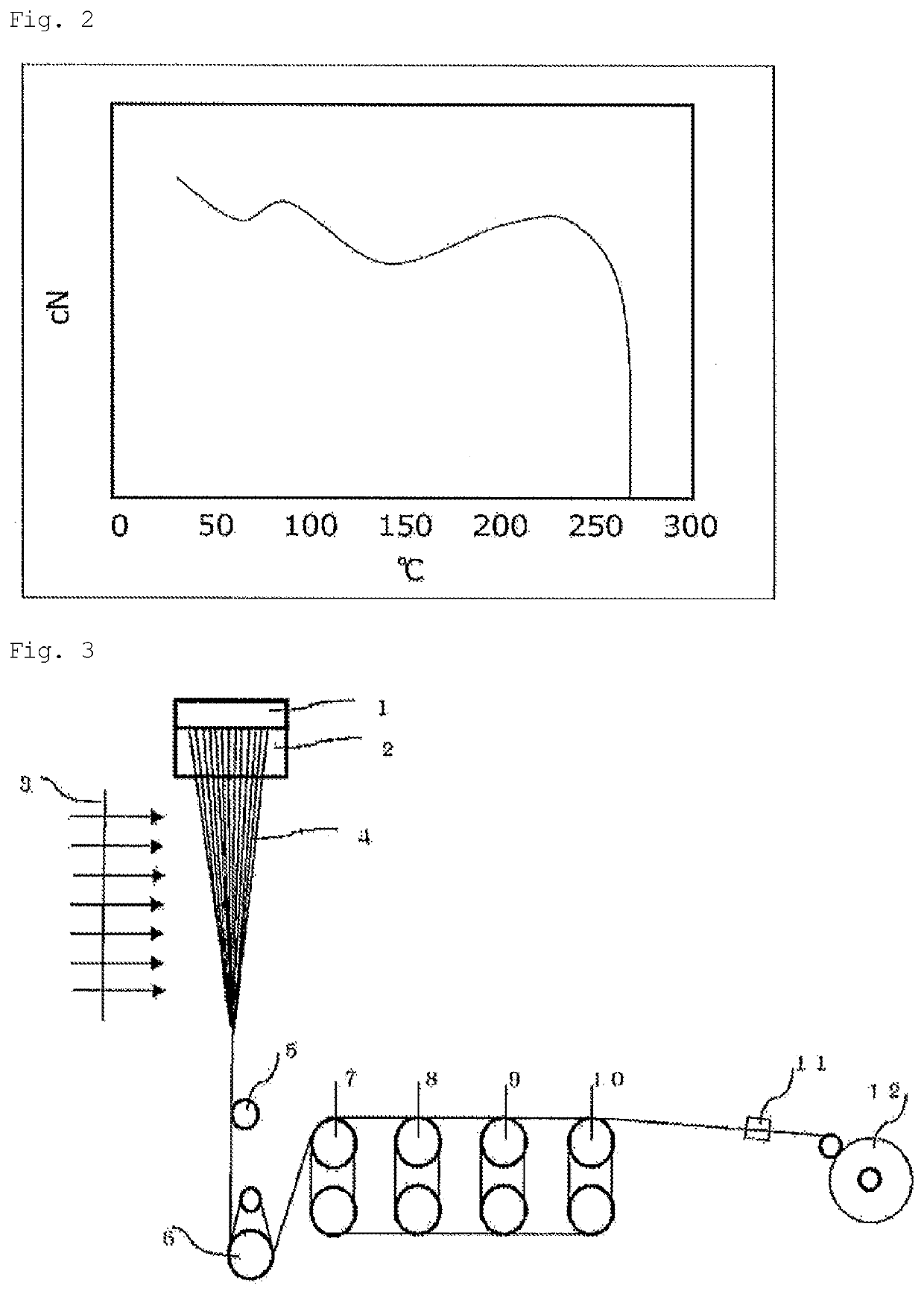
[0122]A nylon 66 polymer in the form of pellets having a relative viscosity RV to sulfonic acid of 3.2 was melted at a temperature of 300° C. using an extruder, then spun using the production equipment shown in FIG. 3. After the molten polymer was homogenized to a temperature of 295° C. using a spin head, the resulting polymer was metered with a gear pump in such a manner that the yarn after winding had a total fineness of 235 dtex; and was spun through a spinneret pack. The spun yarn passed through a 300 mm heat-retention cylinder whose atmospheric temperature was controlled at 260° C., and was solidified by cooling with quenching air whose velocity distribution was controlled at 6% to form yarn at a nozzle draft ratio of 150. After an oil agent was applied to the solidified yarn by a known method, the yarn was taken up by a feed roller without being wound once. The obtained yarn was subjected to cold-drawing at 50° C. and hot-drawing at 180° C., at a cold / hot draw ratio of 2.0. Th...

example 2

[0125]An original yarn was produced under the same conditions as in Example 1, except that the total fineness to be achieved was changed to 270 dtex, and the cold / hot draw ratio was adjusted to 2.2. Table 1 shows physical properties of the obtained original yarn.

[0126]A plain-weave fabric with a weave density of 69 yarns / 2.54 cm for the warp and weft was obtained in the same manner as in Example 1, except that the obtained 270 dtex nylon 66 yarn was used for the warp and weft, the on-machine density was set to 64 yarns / 2.54 cm for both the warp and weft, and the average warp tension was set to 0.23 cN / dtex. Table 2 shows the operational information, physical properties, and appearance quality of the obtained fabric.

[0127]The obtained fabric had few weft insertion errors, excellent loom operation efficiency, and good appearance quality as a final product. Further, the fabric was lightweight and compact, but had sufficient strength characteristics and a high average edgecomb resistanc...

example 3

[0128]A plain fabric was obtained in the same manner as in Example 2, except the average warp tension was adjusted to 0.23 cN / dtex and the loom rotation speed was set to 900 rpm. Table 2 shows the operational information, physical properties, and appearance quality of the obtained fabric.

[0129]The obtained fabric had acceptable levels of operation efficiency and appearance quality as a final product. Further, the fabric was lightweight and compact, but had sufficient strength characteristics and a high average edgecomb resistance retention in the warp and weft directions after heating; and was thus a fabric less susceptible to damage to seams. An airbag fabric with low residual shrinkage and ensured long-term dimensional and physical property stability was thus obtained.


PUM

PropertyMeasurementUnit
residual shrinkageaaaaaaaaaa
thicknessaaaaaaaaaa

Abstract

Problem: To provide an airbag fabric and a coated fabric for airbags that are lightweight and compact while maintaining the tensile strength required for airbags, and that can mitigate damage to seams of an airbag when the airbag deploys; and that allow for stable airbag deployment.Solution: An airbag fabric that is a fabric comprising a synthetic fiber, the fiber that constitutes the fabric having a total fineness of 200 to 400 dtex, an average edgecomb resistance retention in the warp and weft directions after heating at 210° C. for 30 seconds of 60% or more, and a residual shrinkage of 1.5% or less in both the warp and weft directions.

Description

TECHNICAL FIELD[0001]The present invention relates to an airbag fabric and a coated fabric for airbags, which are automotive safety components. More specifically, the present invention relates to an airbag fabric and a coated fabric for airbags that are lightweight and compact, while maintaining the tensile strength required for airbags; that can mitigate damage to seams of airbags during deployment; and that allow for stable airbag deployment.BACKGROUND ART[0002]The demand for a lightweight and compact airbag module system has been growing in recent years because of the need for development to improve the interior space design of vehicles; enhance the visibility of various indicators from the driver's seat; downsize vehicles, while retaining the inside space thereof; and increase fuel efficiency during driving.[0003]An airbag module system is composed of: an airbag mainly comprising a fabric; and a deployment device called an inflator, which instantly deploys an airbag using accumu...

Claims


Application Information

Patent Timeline
Patent Type & Authority Applications(United States)
IPC IPC(8): B60R21/235D03D1/02D06M15/643D06M10/04
CPCD06M10/04B60R21/235D06M15/643D03D1/02D06M10/00
Inventor KAMIMURA, RYUJIAKECHI, TSUTOMU
Owner TOYOBO CO LTD
Why Eureka
Try Eureka