Antenna module

a technology of antenna modules and antenna arrays, applied in the field of antenna modules, can solve the problems of increased communication traffic in wireless networks, increased capacitance components of dividers, and consequently degraded communication speeds and communication quality, so as to reduce parasitic capacitance, achieve the desired impedance, and increase the path

Active Publication Date: 2020-12-17
MURATA MFG CO LTD
View PDF0 Cites 3 Cited by
  • Summary
  • Abstract
  • Description
  • Claims
  • Application Information

AI Technical Summary

Benefits of technology

[0022]In the antenna module according to the present disclosure, since the cavity is provided at the ground electrode, when the antenna module is viewed in plan view, the divider and the ground electrode provided in the dielectric substrate do not overlap. As a result, it is possible to reduce the parasitic capacitance between the divider, in particular, the higher impedance path of the divider, and the ground electrode; this makes it easier to achieve the desired impedance when the antenna module is reduced in thickness. Consequently, it is possible to suppress increase in reflection and loss in the path for communicating radio-frequency signals, and thus, it is possible to hinder degradation of communication characteristics and accomplish downsizing.

Problems solved by technology

As a result, there is a concern that the level of communication traffic in wireless networks is increased and communication speeds and communication quality are accordingly degraded.
In the case in which a divider is provided at a dielectric substrate of an antenna module for the purpose of implementing the Massive MIMO described above, when the height (thickness) of the entire antenna module is decreased, the parasitic capacitance component of the divider is increased and the desired impedance is not achieved, and as a result, it may be difficult to secure the desired communication characteristics.

Method used


Image

  • Antenna module
  • Antenna module
  • Antenna module

Examples


Embodiment Construction

[0038]Hereinafter, an embodiment of the present disclosure is described in detail with reference to the drawings. In the drawings, identical or corresponding portions are assigned identical reference characters, and descriptions thereof are not repeated.

[0039](Basic Configuration of Communication Apparatus)

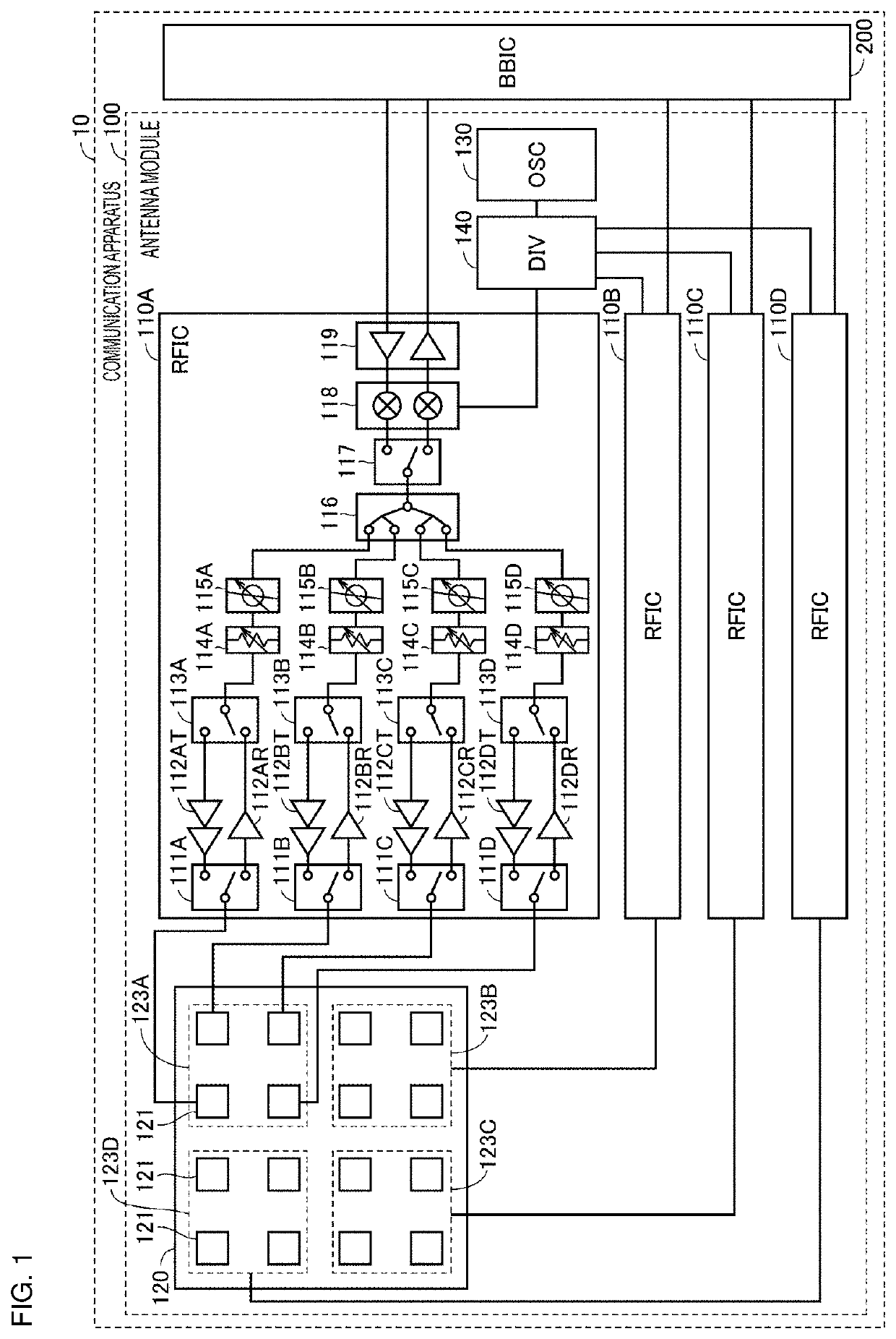
[0040]FIG. 1 is a block diagram of a communication apparatus 10 in which an antenna module 100 according to the present embodiment is used. Examples of the communication apparatus 10 include portable terminals such as a mobile phone, a smartphone, and a tablet computer, and a personal computer having communication functionality.

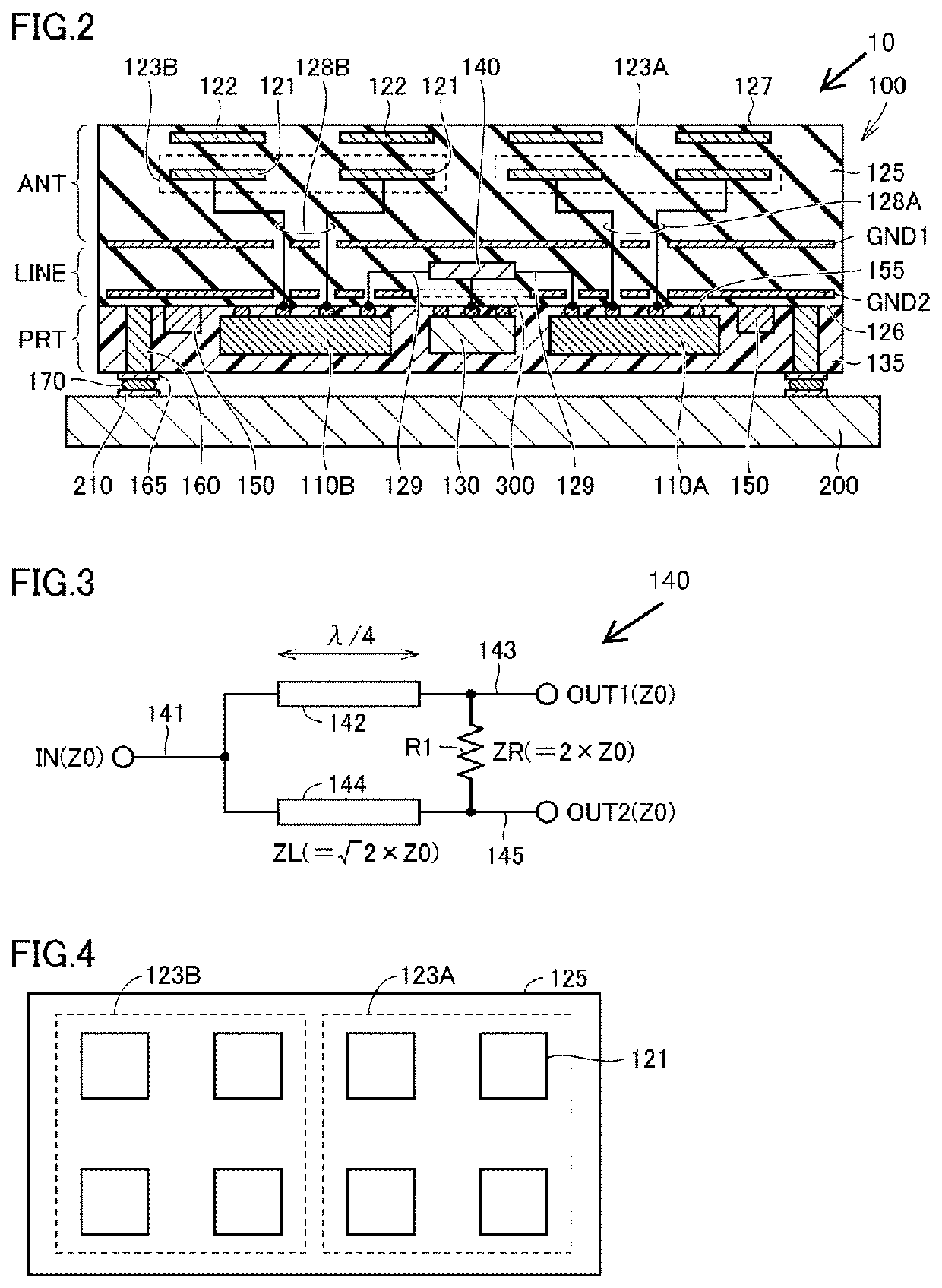
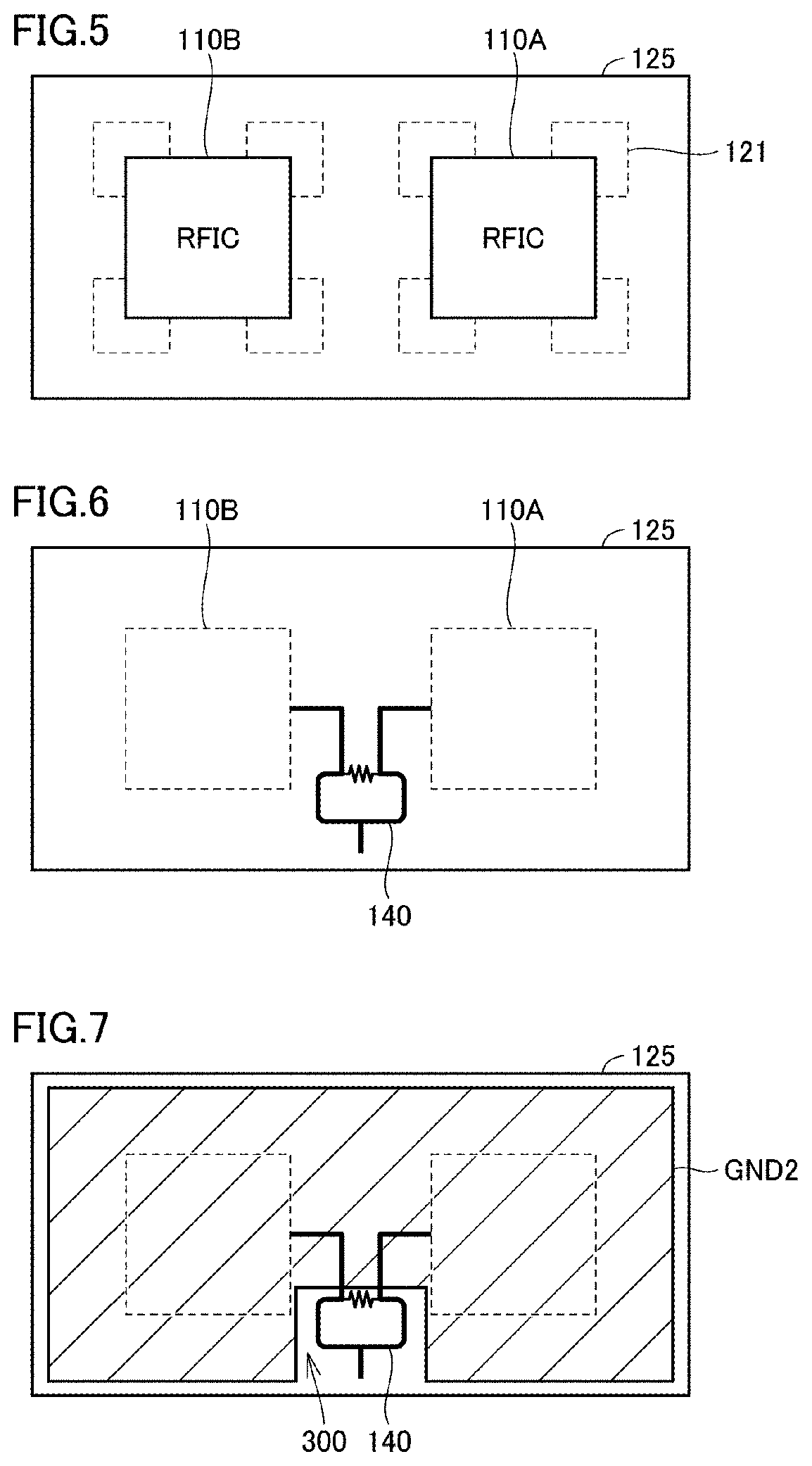
[0041]Referring to FIG. 1, the communication apparatus 10 includes the antenna module 100 and a BBIC 200 forming a baseband-signal processing circuit. The antenna module 100 includes a plurality of radio frequency integrated circuits (RFICs) 110A to 110D, an antenna array 120, an oscillator (OSC) 130, and a divider (DIV) 140. In the communication apparatus ...


PUM


Abstract

An antenna module (100) includes a dielectric substrate (125), antenna groups (123A, 123B) including a plurality of antenna elements (121), RFICs (110A, 110B) configured to supply radio-frequency power to the antenna groups (123A, 123B), a divider (140) configured to divide a radio-frequency signal between the RFICs (110A, 110B), and a ground electrode (GND2). The RFICs (110A, 110B) are mounted at a mounting surface (126) of the dielectric substrate (125). The divider (140) is provided closer to the mounting surface (126) than to the layer in which the antenna groups (123A, 123B) are provided. The divider (140) includes a first path having lower impedance and a second path having higher impedance. When viewed in plan view in a normal-line direction with respect to the mounting surface (126), a cavity (300) is formed at a portion of the ground electrode (GND2), the portion facing the second path.

Description

[0001]This is a continuation of International Application No. PCT / JP2019 / 007018 filed on Feb. 25, 2019 which claims priority from Japanese Patent Application No. 2018-059400 filed on Mar. 27, 2018. The contents of these applications are incorporated herein by reference in their entireties.BACKGROUND OF THE DISCLOSUREField of the Disclosure[0002]The present disclosure relates to an antenna module, and more particularly, to a configuration that hinders characteristic degradation of an antenna module including a plurality of antenna elements.Description of the Related Art[0003]In the field of wireless communication such as portable terminals, the multiple-input and multiple-output (MIMO) technology in which a plurality of antenna elements (for example, 2 to 8 antenna elements) are used at the transmit and receive sides to establish communication is known. Employing the MIMO technology has an advantage in which it is possible to improve data throughput and communication distance without...

Claims


Application Information

Patent Timeline
Patent Type & Authority Applications(United States)
IPC IPC(8): H01Q1/52H01Q21/06
CPCH01Q21/06H01Q1/521H04B1/38H01Q21/0025H01Q1/2283H01P5/16H01Q21/065H01Q3/26H01Q1/52H01Q21/00H01Q1/22
Inventor KURODA, KATSUHITOONAKA, KENGO
Owner MURATA MFG CO LTD
Why Eureka
Try Eureka