An impact mill and a residue processing system incorporating same

a technology of impact mill and residue, which is applied in the direction of mowers, weed killers, threshers, etc., can solve the problems of limiting the food production capacity of agricultural areas around the globe, one of the biggest threats to global food security, and the biggest constraints and costs, so as to reduce the mass flow rate

Pending Publication Date: 2021-01-28
SEED TERMINATOR HLDG PTY LTD
View PDF0 Cites 7 Cited by
  • Summary
  • Abstract
  • Description
  • Claims
  • Application Information

AI Technical Summary

Benefits of technology

[0028](b) a blockage at or reduced mass flow rate from the outlet of the mill.

Problems solved by technology

Weeds and weed control are, and always have been, one of the biggest constraints and costs to grain production.
Weeds are a perpetual problem that limits the food production capacity of agricultural area around the globe.
The herbicide resistance is now widespread and presents one of the biggest threats to global food security.
The residues and contained weed seeds are then spread on the ground to be a problem for next year.
This grain loss has the potential to become a volunteer weed after harvest.
A limitation of the roller mill is the ability to handle the bulk of residue material that contains the weed seeds and thus rely on a separation means to reduce the residue material.
Plant material such as crop residues is fibrous and difficult to process.
A disadvantage of current hammer mills is that the screen which controls particle size distribution determines throughput capacity.
In general, to devitalise weed seeds a small screen size is required and hence throughput capacity is limited.
The impact forces in a cage mill make them suitable for friable or brittle materials and are not widely used for processing fibrous materials.
The arrangement however has limited capacity and cannot process the entire chaff residue fraction exiting the harvesters sieve.
This cage mill is large, heavy, requires a complex counter rotating drive and requires considerable power to operate.
The size, weight and drive, limits options to integrate the cage mill into the harvester.
The rotor bars are narrow with sharp edges resulting in high drag coefficient and turbulence generation.
The stator bars are orientated to result in torque converter or water brake dynamometer like turbulence generation and wasted heat generation.
One disadvantage of this approach is that the stator impact bars take up a lot of space radially.

Method used


Image

  • An impact mill and a residue processing system incorporating same
  • An impact mill and a residue processing system incorporating same
  • An impact mill and a residue processing system incorporating same

Examples


Embodiment Construction

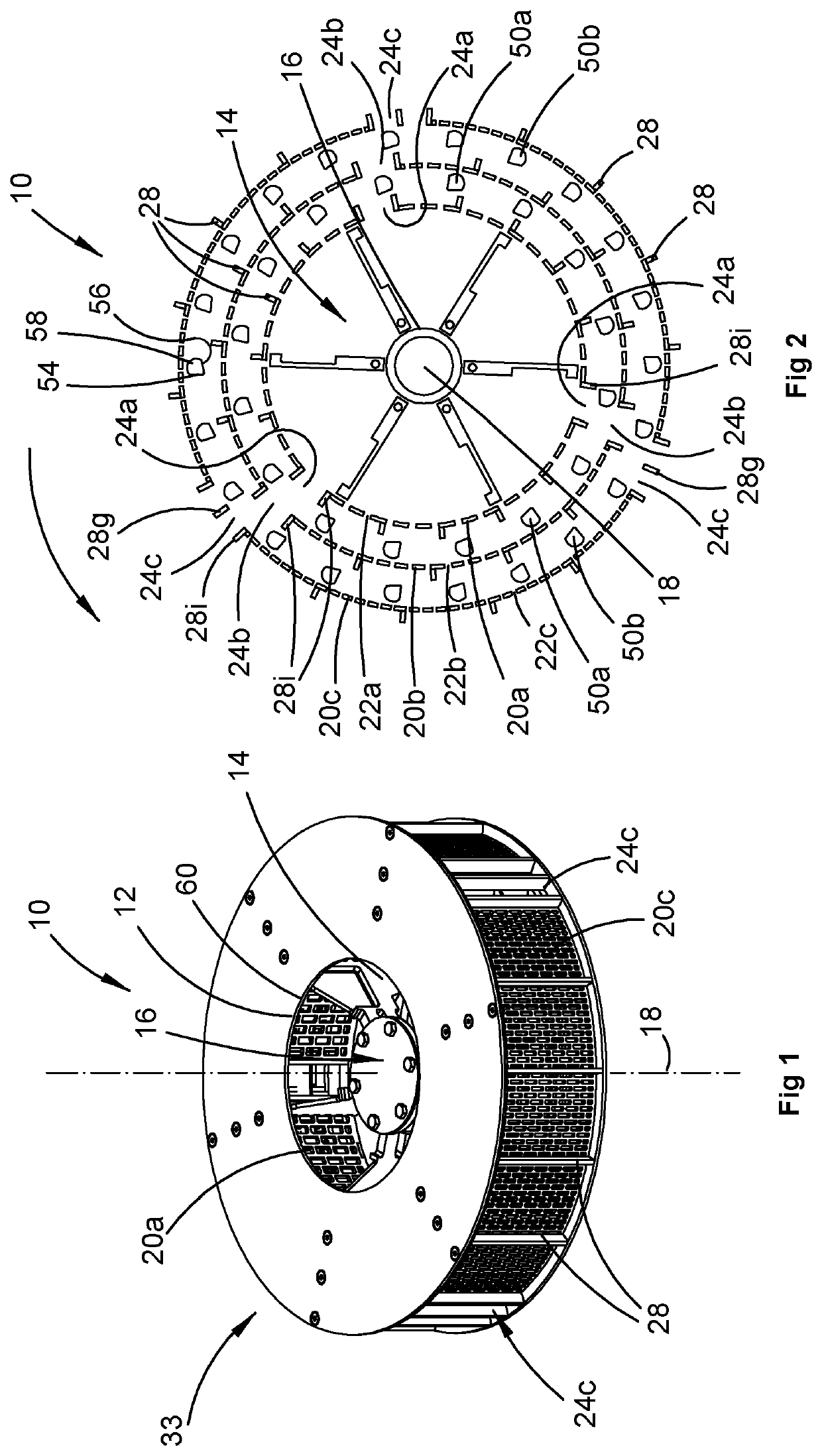
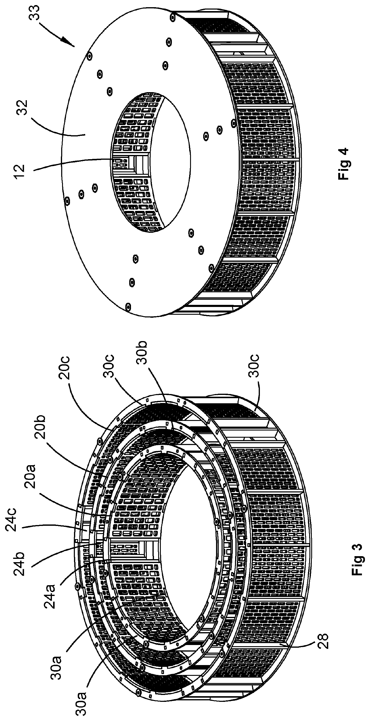
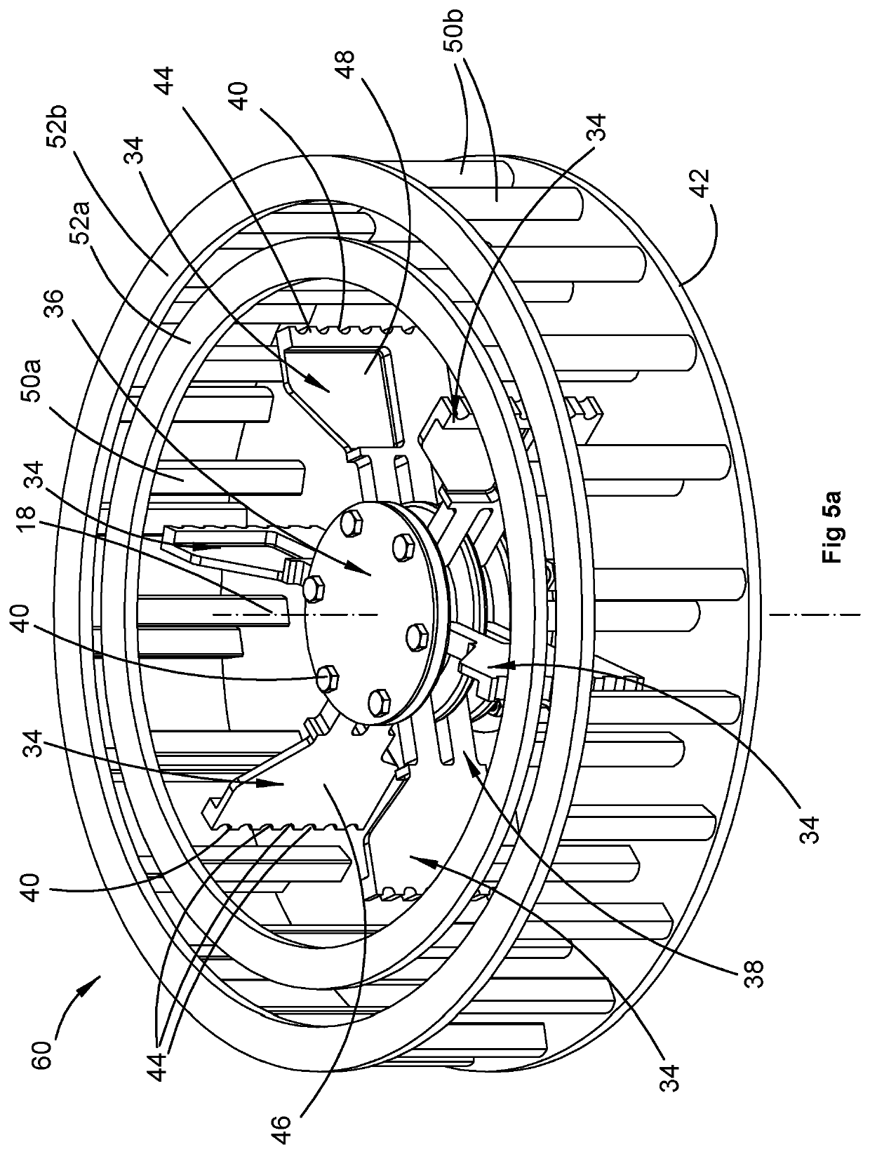
[0090]With reference to the drawings there is shown an embodiment of the disclosed impact mill 10 (FIGS. 1,2 and 6). The Impact mill 10 has an inlet 12 for material to enter the mill and an impact mechanism 16 arranged to rotate about a rotation axis 18. The impact mechanism 16 is operable to pulverise the material after entering through the inlet 12 and discharges the pulverised material through an outlet 154 (FIG. 13a). As explained in greater detail later in this specification the impact mill 10 may include:[0091](a) one or more blockage sensors Bj arranged detect blockage in or reduced mass flow rate of material through the mill; or[0092](b) one or more vibration sensors V1, V2 (FIG. 7a) arranged to sense vibration arising from rotation of the impact mechanism 16 about the rotation axis 18; or[0093](c) both one or more blockage sensors Bj and one or more vibration sensors V1, V2.

[0094]As seen in FIGS. 1, 2 and 6 an embodiment of the disclosed an impact mill may be in the form of...


PUM


Abstract

An impact mill (10) has an inlet (12) for material to enter the mill, an impact mechanism (16, 50) arranged to rotate about a rotation axis and being operable to pulverise the material after entering through the inlet, and an outlet (154) for discharge of pulverised material. Blockage sensors (Bj), vibration sensors V, torque sensors Tn, temperature sensors and proximity sensors may be selectively incorporated into the mill.

Description

TECHNICAL FIELD[0001]An impact mill of a type suitable for the devitalisation of weed seeds and fragmentation of organic matter is disclosed. The impact mill in a preferred form is a multistage hammer mill. Also disclosed is a residue processing system which incorporates one or more impact mills or alternate residue processing devices.BACKGROUND ART[0002]Weeds and weed control are, and always have been, one of the biggest constraints and costs to grain production. Weeds are a perpetual problem that limits the food production capacity of agricultural area around the globe. Weeds compete with the cultivated crops for water, sunlight and nutrients. In the past 50 years there has been a shift from tillage being the most important method to control weeds to herbicides being the most important tool to control weeds. Herbicides in general provide much better control of weeds than tillage methods and do not have the major issues of soil erosion, moisture loss and breakdown of soil structure...

Claims


Application Information

Patent Timeline
Patent Type & Authority Applications(United States)
IPC IPC(8): A01D43/10B02C13/31B02C13/18B02C21/02A01M21/02A01D41/127
CPCA01D43/102B02C13/31B02C13/1807B02C2021/023A01M21/02A01D41/1276A01D41/1271B02C21/026B02C25/00A01F12/44A01D41/1272A01D41/1274A01F12/40B02C13/284B02C13/20B02C13/16B02C13/185B02C13/1835
Inventor BERRY, NICHOLAS KANE
Owner SEED TERMINATOR HLDG PTY LTD
Why Eureka
Try Eureka