Spectral analysis system, mobile device having a spectral analysis system, method for determining a correction function for the imaging correction of a spectrum captured by a spectral analysis system, and computer program

a spectral analysis system and mobile device technology, applied in the direction of spectrometry/spectrophotometry/monochromators, optical radiation measurement, instruments, etc., can solve the problems of complex optical functional surfaces, narrow tolerances, and large mechanical effort of mechanical actuators, and achieve small tolerances of optics, increase the spectral resolution of the spectral apparatus, and reduce the effect of manufacturing costs

Active Publication Date: 2021-01-28
FRAUNHOFER GESELLSCHAFT ZUR FOERDERUNG DER ANGEWANDTEN FORSCHUNG EV
View PDF0 Cites 4 Cited by
  • Summary
  • Abstract
  • Description
  • Claims
  • Application Information

AI Technical Summary

Benefits of technology

[0018]This embodiment of the spectrometer is based on the finding that, by applying the correction function to the captured spectrum, aberrations of the optic of the spectrometer may be compensated to such an extent that aberrations of the spectrometer no longer have to be compensated by mechanically adjusting components of the spectrometer, such as the optic. For example, the captured spectra may be processed by means of the spectral analysis system such that the spectrometer with aberrations comprises a corrected spectrum that differs only slightly from the spectrum actually to be captured. Thus, with this spectrometer, it is possible to increase the spectral resolution of the spectral apparatus by applying the correction function to the captured spectrum. The corrected spectrum of the spectrometer is more similar to the spectrum actually to be captured than the captured spectrum. In addition, for example, the spectrometer may be produced in large quantities and as a very small system, since, with this spectrometer, aberrations of the optic no longer have to be rectified afterwards by adjustment and very small tolerances of the optic no longer have to be accepted. For example, due to the fact that the optic may comprise large tolerances, it is easier to produce the individual components of the spectrometer and to subsequently assemble them, enabling mass production. In addition, the spectrometer described herein enables production of the spectrometer as a very small system. The smaller the production size of a spectrometer tends to be, the smaller the tolerance requirements of the optic of the spectrometer. Due to the small tolerance requirements of the components of the spectrometer, such as the optic, the production of small spectrometers is a very elaborate and cost-intensive. In addi...

Problems solved by technology

Although very often used, these two measures have disadvantages.
The correction of aberrations of the optic often leads to complex optical functional surfaces and narrow tolerances.
The use of mechanical actuators represents a considerable additional mechanical effort and therefore additional costs, and it furthermore prevents mass production of spectral apparatuses, since an adjustment process is very time consuming.
Strictly speaking, however, this approach is not an improvement/increase of the spectral resolution of certain types of devices, but rather a constructive assurance of the same.
In any case, the usual method for miniaturized systems and high quantities does not lead to the desired result.
However, this method involves the comparison of spectra of the same samples captured with different spectral apparatuses and possibly leads to comparatively complex data processing.
However, the methods used in this context are only applicable to a very limited extent to spectral apparatuses, since questions of wavelength calibrations that are not relevant for the above-mentioned applications have to be considered here.
Furthermore, in the examples mentioned above, these methods are usually not specifically included in the optimization process of the hardware, but are used to solve...

Method used


Image

  • Spectral analysis system, mobile device having a spectral analysis system, method for determining a correction function for the imaging correction of a spectrum captured by a spectral analysis system, and computer program
  • Spectral analysis system, mobile device having a spectral analysis system, method for determining a correction function for the imaging correction of a spectrum captured by a spectral analysis system, and computer program
  • Spectral analysis system, mobile device having a spectral analysis system, method for determining a correction function for the imaging correction of a spectrum captured by a spectral analysis system, and computer program

Examples


Embodiment Construction

[0038]Before embodiments of the present invention are subsequently described in more detail on the basis of the drawings, it is to be noted that identical or functionally identical elements, objects and / or structure, or elements, objects and / or structures with the same effect are provided in the different drawings with the same reference numerals so that the description of these elements illustrated in different embodiments is interchangeable, or may be applied to one another.

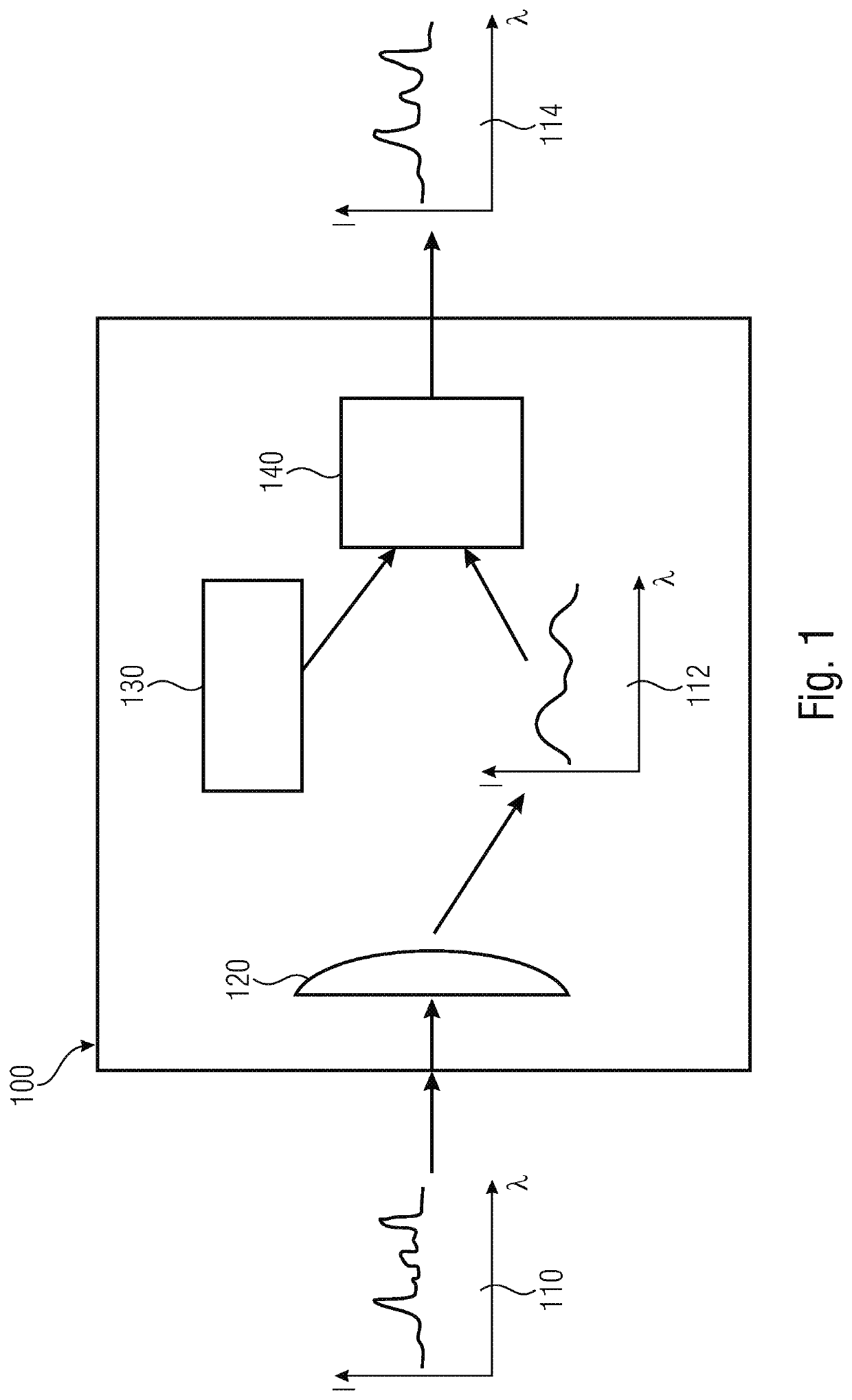
[0039]FIG. 1 shows a schematic illustration of a spectral analysis system 100 according to an embodiment of the present invention for capturing a spectrum 110 to be captured with an imaging optic 120. For example, the spectral analysis system, in the following referred to as spectrometer 100, includes a memory 130 having stored therein a correction function. In addition, e.g., the spectrometer 100 includes a processing means 140 for applying the correction function to a captured spectrum 112 so as to obtain a c...


PUM


Abstract

Spectral analysis system for capturing a spectrum with an optic that forms an optical path. The spectral analysis system is configured to apply a correction function to a captured spectrum so as to obtain a modified spectrum.

Description

CROSS-REFERENCES TO RELATED APPLICATIONS[0001]This application is a continuation of copending International Application No. PCT / EP2019 / 058827, filed Apr. 8, 2019, which is incorporated herein by reference in its entirety, and additionally claims priority from German Application No. DE 10 2018 205 400.2, filed Apr. 10, 2018, which is incorporated herein by reference in its entirety.[0002]Embodiments according to the invention relate to a spectrometer, a mobile device with a spectrometer, a method for determining a correction function for the imaging correction of a spectrum captured by a spectrometer, and a computer program.BACKGROUND OF THE INVENTION[0003]Different methods for improving / increasing the spectral resolution in spectral apparatuses are known in the conventional technology.[0004]The traditional, therefore widely used, method is based on a careful aberration correction during the optical calculation on the one hand, and on adjustment processes, in particular a focus adjus...

Claims


Application Information

Patent Timeline
IPC IPC(8): G01J3/28G01J3/10
CPCG01J3/2823G01J3/0208G01J3/10G01J3/2803G01J3/0286G01N21/274
Inventor KNOBBE, JENSGRUEGER, HEINRICH
Owner FRAUNHOFER GESELLSCHAFT ZUR FOERDERUNG DER ANGEWANDTEN FORSCHUNG EV
Why Eureka
Try Eureka