Electrode with enhanced state of charge estimation

Active Publication Date: 2021-02-04
GM GLOBAL TECH OPERATIONS LLC
0 Cites 0 Cited by

AI-Extracted Technical Summary

Problems solved by technology

However, for some battery chemistry that have long and flat charge/discharge plateau, ...

Benefits of technology

[0004]Thus, while current lithium-ion batteries achieve their i...

Abstract

An anode electrode with enhanced state of charge estimation is provided. The anode electrode comprises anode layer and a negative current collector. The negative current collector has a first side and a second side. The anode layer comprises lithium-titanium oxide and a second anode material (e.g. niobium-titanium oxide) disposed on at least one of the first and second sides of the negative current collector with single-layer or layer-by-layer coated structures. The second anode material (e.g. niobium-titanium oxide) can be physically blended with lithium-titanium oxide or be at least partially coated on the surface of lithium-titanium oxide or their combinations. The anode electrode further comprises a binder and a conductive carbon.

Application Domain

Negative electrodesElectrode collector coating +1

Technology Topic

PhysicsState of charge +6

Image

  • Electrode with enhanced state of charge estimation
  • Electrode with enhanced state of charge estimation
  • Electrode with enhanced state of charge estimation

Examples

  • Experimental program(1)

Example

[0030]The following description is merely exemplary in nature and is not intended to limit the present disclosure, application, or uses.
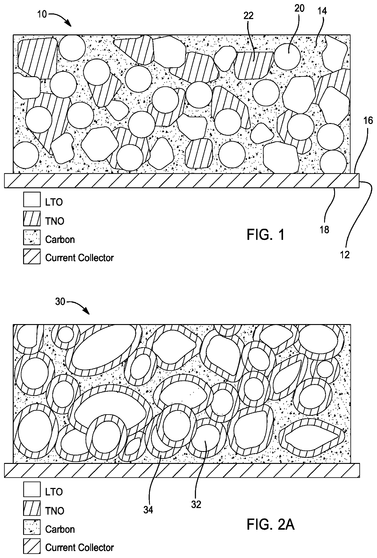
[0031]Referring to FIG. 1, an anode electrode 10 for a battery with enhanced state of charge estimation is provided in accordance with one embodiment of the present disclosure. As shown, the anode electrode 10 comprises a negative current collector 12 and an anode layer 14. In this embodiment, the negative current collector 12 has a first side 16 and a second side 18. Moreover, the negative current collector is comprised of a conductive material such as metal, metal alloy, or any other suitable material.
[0032]Preferably, the anode layer 14 is disposed on at least one of the first and second sides 16, 18 of the negative current collector 12. As shown, the anode layer 14 is disposed on the first side 16 of the negative current collector 12. In this embodiment, the anode layer 14 comprises lithium-titanium oxide 20 and a second anode material (e.g. niobium-titanium oxide) 22. On a materials level, the anode layer 14 preferably comprises a weight ratio of lithium-titanium oxide to a second anode material (e.g. niobium-titanium oxide) of about 99% to about 1%.
[0033]FIGS. 2A and 2B depict an anode electrode 30 in accordance with another embodiment of the present disclosure. As shown, the lithium-titanium oxide 32 is at least partially coated with a second anode material (e.g. niobium-titanium oxide) 34. Referring to FIG. 2A, lithium-titanium oxide 32 is fully coated by a second anode material (e.g. niobium-titanium oxide) 34. Referring to FIG. 2B, lithium-titanium oxide 32 is partially coated by a second anode material (e.g. niobium-titanium oxide) 34. As will be described in greater detail below, the degree of coating of the lithium-titanium oxide with a second anode material (e.g. niobium-titanium oxide) is related to a molar ratio of a niobium precursor and titanium precursor used in preparing the electrode. The weight ratio of lithium-titanium oxide to a second anode material (e.g. niobium-titanium oxide) of about 99% to about 1%.
[0034]As shown in FIG. 3, an electrode 40 comprises a negative current collector 42 and an anode layer 44 having a first layer 46 and a second layer 48. Preferably, the first layer 46 has lithium-titanium oxide only or lithium-titanium oxide and a second anode material (e.g. niobium-titanium oxide) in a weight ratio of between 0 to 1. The second layer 48 may comprise a second anode material (e.g. niobium-titanium oxide) only or a second anode material (e.g. niobium-titanium oxide) and lithium-titanium oxide in another weight ratio of between 0 to 1. In this embodiment, the second layer (a second anode material (e.g. niobium-titanium oxide) only) and the first layer (lithium-titanium oxide only) have a weight ratio of between about 0.01 to about 0.99.
[0035]As shown, the first layer 46 is disposed on a first side 50 of the negative current collector 42 and the second layer 48 is disposed on the first layer 46 such that the first layer 46 is disposed between the second layer 48 and first side 50 of the negative current collector 42.
[0036]As shown in FIG. 4, the second layer 48 is disposed on the first side 50 of the negative current collector 42 and wherein the first layer 46 is disposed on the second layer 48 such that the second layer 48 is disposed between the first layer 46 and first side 50 of the negative current collector 42.
[0037]As shown in FIG. 5, the first layer 46 is disposed on the first side 50 of the negative current collector 42 and the second layer 48 is disposed on the second side 52 of the negative current collector 42 such that the current collector 42 is disposed between the first layer 46 and the second layer 48.
[0038]FIG. 6 illustrates a battery 60 with enhanced state of charge estimation in accordance with another embodiment of the present disclosure. As shown, on a material level, the battery 60 comprises a positive electrode 62, a negative electrode 64, and a separator 66. The positive electrode 62 comprises a cathode layer 68 and a positive current collector 70 comprising a conductive material. The negative electrode 64 comprises anode layer 72 and a negative current collector 74 comprising a conductive material. As shown, the negative current collector 74 has a first side 76 and a second side 78.
[0039]In this embodiment, the anode layer 72 comprises lithium-titanium oxide and a second anode material (e.g. niobium-titanium oxide) disposed on at least one of the first and second sides 76, 78 of the negative current collector 74. The anode layer 72 comprises a weight ratio of lithium-titanium oxide to a second anode material (e.g. niobium-titanium oxide) of about 99% to about 1%. As shown, the separator layer 66 is disposed between the positive electrode 62 and the negative electrode 64. In some embodiments, the battery further comprises a binder and a conductive carbon.
[0040]On a material level, the lithium-titanium oxide is at least partially coated with a second anode material (e.g. niobium-titanium oxide). As will be described in greater detail below, the degree of coating of the lithium-titanium oxide with a second anode material (e.g. niobium-titanium oxide) is related to a molar ratio of a niobium precursor and titanium precursor used in preparing the electrode.
[0041]As in the previous embodiments, the anode layer may comprise a first layer and a second layer. As previously provided, the first layer may comprise lithium-titanium oxide only or lithium-titanium oxide and a second anode material (e.g. niobium-titanium oxide) in one weight ratio of between 0 to 1. The second layer 48 may comprise a second anode material (e.g. niobium-titanium oxide) only or a second anode material (e.g. niobium-titanium oxide) and lithium-titanium oxide in another weight ratio of between 0 to 1.
[0042]In one embodiment on an electrode level, the first layer may be disposed on the first side of the negative current collector. The second layer may be disposed on the first layer such that the first layer is disposed between the second layer and first side of the negative current collector.
[0043]In another embodiment, the second layer may be disposed on the first side of the negative current collector. The first layer is disposed on the second layer such that the second layer is disposed between the first layer and first side of the negative current collector.
[0044]In yet another embodiment, the first layer may be disposed on the first side of the negative current collector. The second layer may be disposed on the second side of the negative current collector such that the current collector is disposed between the first layer and the second layer.
[0045]FIG. 7 illustrates a method 80 of making an electrode for a battery with enhanced state of charge estimation in accordance with another example of the present disclosure. As shown, the method 80 comprises a step 82 of mixing a niobium precursor, a titanium precursor, lithium titanium oxide, and a solvent to define a precursor solution. In this embodiment, the niobium precursor may comprise at least one of NbCl5, C10H25O5Nb, and C20H45O5Nb etc. and the titanium precursor may comprise at least one of C16H36O4Ti and C12H28O4Ti etc..
[0046]As shown in FIG. 7, the method further comprises a step 84 of drying the precursor solution at between about 600 C and about 1200 C for between 5 to 15 hours to remove the solvent. As a result, the step of drying defines or produces an electrode material comprising lithium-titanium oxide and a second anode material (e.g. niobium-titanium oxide). In one embodiment, the lithium-titanium oxide and the electrode material have a weight ratio of between about 0.01 to about 0.99. As shown, the method further comprises a step 86 of coating the electrode material on at least one side of a negative current collector, resulting in the electrode.
[0047]On a material level, the lithium-titanium oxide of the electrode material is at least partially coated with a second anode material (e.g. niobium-titanium oxide) in one embodiment. It is understood that the degree of coating of the lithium-titanium oxide with a second anode material (e.g. niobium-titanium oxide) is directly related to molar ratio of the niobium precursor and titanium precursor. In this embodiment, the niobium precursor and titanium precursor have a molar ratio of between about 1:1 and about 5:1.
[0048]In one aspect of the present disclosure, the step of mixing comprises mixing the solvent with lithium-titanium oxide and one of the niobium precursor and the titanium precursor (e.g. niobium precursor), defining a solution. The method further comprises, while stirring the solution, adding the other of the niobium precursor and the titanium precursor (e.g. titanium precursor) to define the precursor solution. In other words, the other of the two (the niobium precursor, the titanium precursor) is then added to the solution while stirring. For example, if the niobium precursor and the lithium-titanium oxide are mixed with the solvent, then the titanium precursor is added to the solution, while stirring, to define the precursor solution.
[0049]The description of the present disclosure is merely exemplary in nature and variations that do not depart from the gist of the present disclosure are intended to be within the scope of the present disclosure. Such variations are not to be regarded as a departure from the spirit and scope of the present disclosure.

PUM

no PUM

Description & Claims & Application Information

We can also present the details of the Description, Claims and Application information to help users get a comprehensive understanding of the technical details of the patent, such as background art, summary of invention, brief description of drawings, description of embodiments, and other original content. On the other hand, users can also determine the specific scope of protection of the technology through the list of claims; as well as understand the changes in the life cycle of the technology with the presentation of the patent timeline. Login to view more.

Similar technology patents

Semiconductor devices with reduced impact from alien particles

InactiveUS7199431B2improve design
Owner:TAIWAN SEMICON MFG CO LTD

Spring-loaded leg base

InactiveUS20190313797A1improve design
Owner:ZENITHEN USA

Image Capture Device

InactiveUS20090219431A1cost reductionimprove design
Owner:FUNAI ELECTRIC CO LTD

Storing box

InactiveCN101581527AImprove design
Owner:TWINBIRD CORP

Resonant cavity surface acoustic wave (SAW) filters

PendingUS20210265980A1improve designgood performance
Owner:FRECNSYS

Classification and recommendation of technical efficacy words

  • improve design

Venturi outlet turbine airfoil

InactiveUS6969230B2increase efficiencyimprove design
Owner:GENERAL ELECTRIC CO

Organic light emitting display and fabricating method thereof

InactiveUS20080111125A1improve design
Owner:SAMSUNG DISPLAY CO LTD

Nailer with improved spacer actuator

InactiveUS6918523B1reduce space considerablyimprove design
Owner:YONG SONG HARDWARE & TOOL

Knitted fabric with pockets and knitting method with pockets

ActiveCN109778410AImprove designgood looking
Owner:SHIMA SEIKI MFG LTD

Safety system

ActiveUS20120240707A1improve design
Owner:PACHOV YAVOR
Why Eureka
Try Eureka