Low friction resin composites
a resin composite and low friction technology, applied in the field of resin composites, can solve the problems of fuel use, pai and pi are limited in application, and 10% of pai is lost, and achieve the effects of excellent heat resistance, excellent durability, and low friction property
- Summary
- Abstract
- Description
- Claims
- Application Information
AI Technical Summary
Benefits of technology
Problems solved by technology
Method used
Image
Examples
preparation example 1
onitrile Compound (PN1)
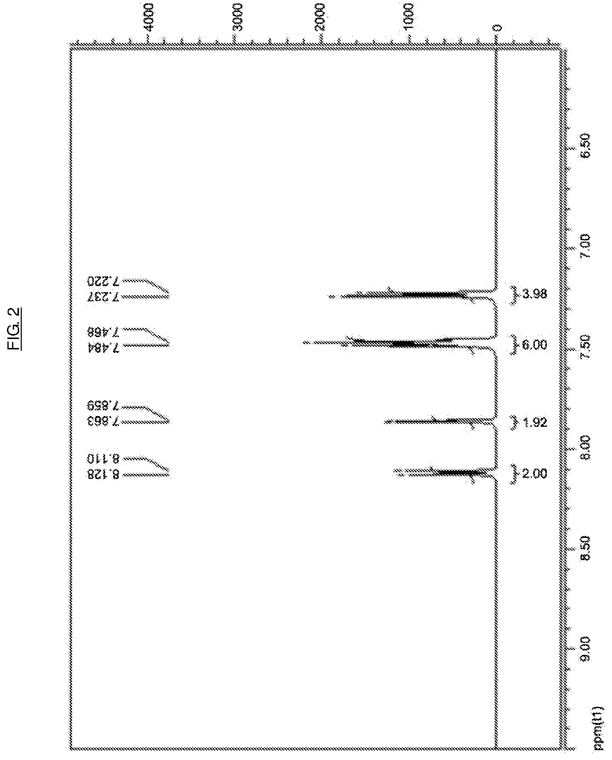
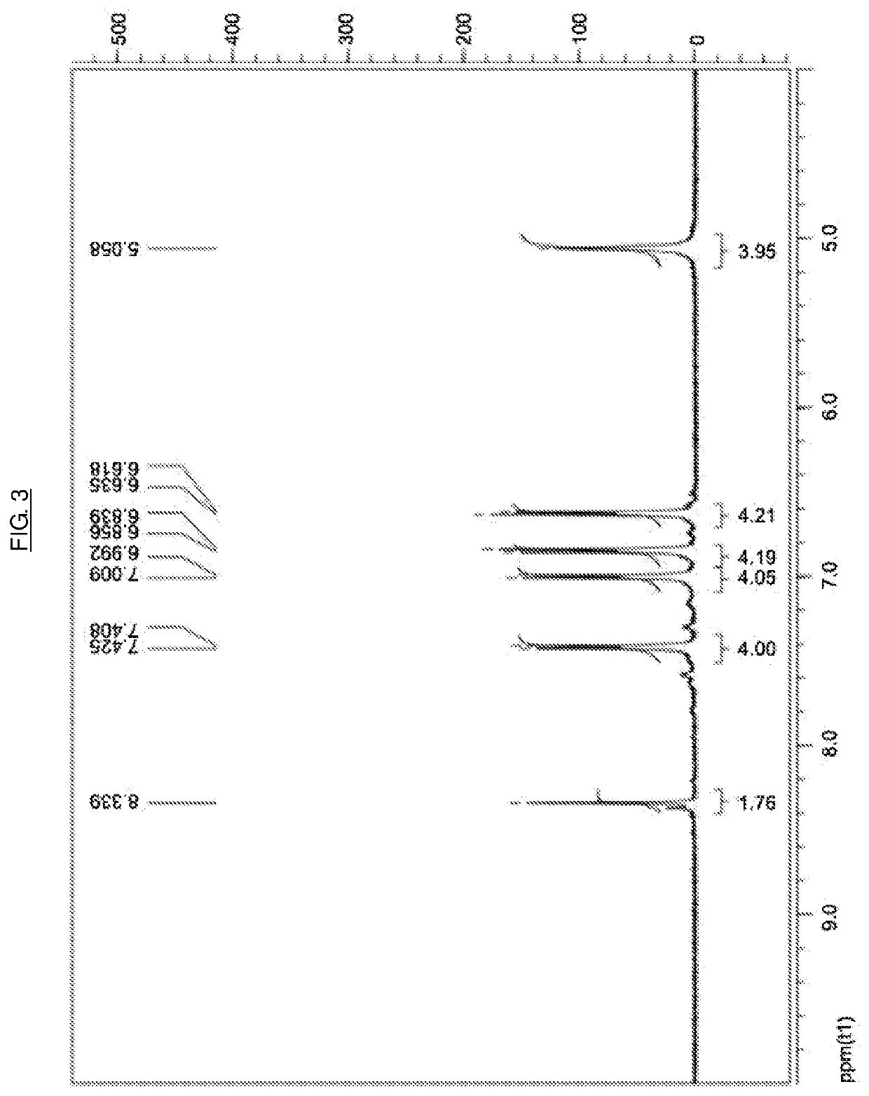
[0223]The compound of the following Chemical Formula A1 (PN1) was synthesized as follows.
[0224]32.7 g of the compound of the following Chemical Formula A2 and 120 g of DMF (Dimethyl Formamide) were introduced into a 3 neck round bottom flask, and stirred at room temperature to dissolve. Subsequently, 51.9 g of the compound of the following Chemical Formula A3 was added, and 50 g of DMF was added, and then, stirred to dissolve. Subsequently, 62.2 g of potassium carbonate and 50 g of DMF were introduced together, and the temperature was raised to 85° C. while stirring. After reacting for about 5 hours, the solution was cooled to room temperature. The cooled reaction solution was poured into the aqueous solution of 0.2 N hydrochloric acid to neutralize and precipitate, and after filtering, washed with water. Thereafter, the filtered reactant was dried in a vacuum oven of 100° C. for a day, water and remaining solvents were removed, and then, the compound of the f...
preparation example 2
Agent Compound (CA1)
[0225]A compound of the following Chemical Formula A14 (CA1) was synthesized by dehydrogenation condensation of diamine and dianhydride. 24 g of 4,4′-oxydianiline and 40 g of NMP (N-methyl-pyrrolidone) were introduced into a 3 neck round bottom flask, and stirred at room temperature to dissolve. The solution was cooled with a water bath, and 8.7 g of a compound of the following Chemical Formula A15 was gradually introduced together with 40 g of NMP in three portions. When the introduced compounds were completely dissolved, 16 g of toluene was added to the reactant to form an azeotrope. Dean-Stark equipment and a reflux condenser were installed, and the Dean-Stark equipment was filled with toluene. 4.2 mL of pyridine was introduced as a dehydrogenation condensation catalyst, a temperature was raised to 170° C., and the solution was stirred for 3 hours. While removing water generated with the formation of an imide ring with the Dean Stark equipment, the solution wa...
preparation example 3
Agent Compound (CA2)
[0226]A compound of the following Chemical Formula A18 (CA2) was synthesized by dehydrogenation condensation of diamine and dianhydride. 8.1 g of a compound of the following Chemical Formula A16 (m-phenylene diamine) and 50 g of NMP (N-methyl-pyrrolidone) were introduced into a 3 neck round bottom flask, and stirred at room temperature to dissolve. The solution was cooled with a water bath, and 26 g of a compound of the following Chemical Formula A17 was gradually introduced together with 60 g of NMP in three portions. When the introduced compounds were completely dissolved, 23 g of toluene was added to the reactant to form an azeotrope. Dean-Stark equipment and a reflux condenser were installed, and the Dean-Stark equipment was filled with toluene. 5.2 mL of pyridine was introduced as a dehydrogenation condensation catalyst, the temperature was raised to 170° C., and the solution was stirred for 3 hours. While removing water generated with the formation of an im...
PUM
| Property | Measurement | Unit |
|---|---|---|
| diameter | aaaaa | aaaaa |
| friction | aaaaa | aaaaa |
| weight | aaaaa | aaaaa |
Abstract
Description
Claims
Application Information
 - R&D
- Intellectual Property
- Life Sciences
- Materials
- Tech Scout
- Unparalleled Data Quality
- Higher Quality Content
- 60% Fewer Hallucinations
Browse by: Latest US Patents, China's latest patents, Technical Efficacy Thesaurus, Application Domain, Technology Topic, Popular Technical Reports.
© 2025 PatSnap. All rights reserved.Legal|Privacy policy|Modern Slavery Act Transparency Statement|Sitemap|About US| Contact US: help@patsnap.com


