Method and System for Quality Assurance and Control of Additive Manufacturing Process

a technology of additive manufacturing and quality assurance, applied in the field of additive manufacturing of three-dimensional objects, can solve the problems of reducing reducing processing times, and requiring far less processing power for real-time feedback control of the fabrication process, so as to reduce the amount of data processing, reduce processing times, and less processing power

Active Publication Date: 2021-03-18
MONASH UNIV
View PDF0 Cites 9 Cited by
  • Summary
  • Abstract
  • Description
  • Claims
  • Application Information

AI Technical Summary

Benefits of technology

[0015]Locating potential defects from a single image rather than a large set of images captured at high frame rates dramatically reduces the amount of data processing. This in turn reduces processing times such that real time feedback control of the fabrication process requires far less processing power. As discussed further below, multiple image sensors allow a scalable system with much higher image resolution than otherwise possible.
[0017]The use of multiple cameras allows increased image resolution of the image without resorting to expensive image sensors with large sensor arrays. The system is scalable in the sense that adding more image sensors extends the field of view. Furthermore, overlapping image data of the same sub-region, from different image sensors, is also useful for noise calibration. In contrast, single camera systems would need to use a wide angle lens, and / or a more elevated position to extend field of view. However, there are restrictions on the space surrounding powder bed fusion machines and wide angle lenses, or ‘fish-eye’ lenses, introduce detrimental image distortions and lower resolution.
[0018]The data captured by each image sensor is a spatially resolved image of the energy input in part of the specified area. When merged with the image data from the other image sensors, a single image with a relatively small amount of spatially resolved image data is indicative of the energy input across the whole area of interest within that layer of material. The comparison between this single image and a reference image requires little processing power and allows real-time feedback control of the laser or electron beam. Smaller data volumes are more easily stored, or used to develop a 3D defect map of the component.
[0033]Preferably, the image sensors are positioned directly above the layer of material such that their optical axes are normal to the layer. In this case, the system is integrated into the PBF equipment during assembly. Being directly above the power layer reduces the need to correct for perspective.

Problems solved by technology

Locating potential defects from a single image rather than a large set of images captured at high frame rates dramatically reduces the amount of data processing.
This in turn reduces processing times such that real time feedback control of the fabrication process requires far less processing power.

Method used


Image

  • Method and System for Quality Assurance and Control of Additive Manufacturing Process
  • Method and System for Quality Assurance and Control of Additive Manufacturing Process
  • Method and System for Quality Assurance and Control of Additive Manufacturing Process

Examples


Embodiment Construction

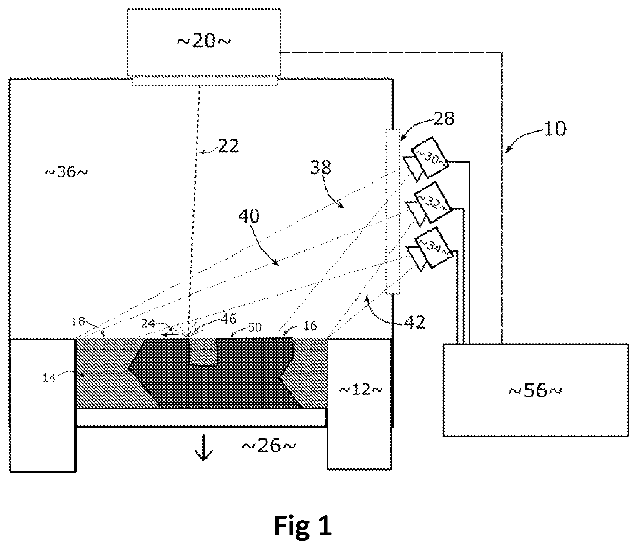
lass="d_n">[0074]Referring to FIG. 1, the selective laser melting system 10 progressively builds a three dimensional component 16 layer by layer from solidifying selected areas of powder material sequentially deposited in layers 14 movable build platform 12 within a build chamber 36. Build chamber 36 has a viewing window 28 (typically a semitransparent laser safe window) for safely observing the build process.

[0075]The top most layer 18 of powdered material is exposed to a laser beam 22 from a scanning laser head 20. A laser beam 22 scans across the powder layer 18 in the direction indicated by arrow 24 in a predetermined raster pattern. A laser melt pool 46 forms where the laser beam 22 is incident with the powdered material. The melt pool 46 travels with the laser beam 22 as it scans through the raster pattern leaving behind melted material to cool and solidify. Once the predetermined raster pattern has been completed, a fresh layer of powdered material is deposited as the floor 2...


PUM

PropertyMeasurementUnit
wavelengthaaaaaaaaaa
wavelengthsaaaaaaaaaa
diameteraaaaaaaaaa

Abstract

An additive manufacturing system and method is provided for fabricating 3D objects (16) from successive layers (14) of material. The additive manufacturing system (10) has an energy projection assembly (20) for inputting energy (22) into a specified area within the layer (18) to consolidate the material; a plurality of image sensors (30, 32, 34), each of the image sensors having a corresponding field of view (35, 40, 42) covering at least part of the layer (18) of material, such that each of the fields of view at least partially overlap with the field of view of at least one other of the image sensors; and an image processor (56) to capture image data from each of the image sensors (30, 32, 34). The image processor (56) controls exposure times for each of the image sensors (30, 32, 34) and combines the image data from the image sensors to provide a single, spatially resolved image of the energy being input throughout the specified area for each layer (14) of material respectively for comparison against threshold data values to locate potential consolidation defects in the specified area.

Description

FIELD OF THE INVENTION[0001]The present invention relates to additive manufacturing of three dimensional objects by sequentially depositing and consolidating layers of the object. In particular, the invention relates to powder bed fusion (PBF) such as selective laser sintering (SLS), electron beam melting (EBM) and selective laser melting (SLM).BACKGROUND OF THE INVENTION[0002]Selective laser sintering (SLS), selective laser melting (SLM), electron beam melting (EBM) are types of powder bed fusion (PBF) manufacturing. Successive layers of a raw material in powder form are deposited and solidified in specified areas (corresponding to a layer of the three dimensional object) until the three dimensional object is complete. This allows the fabrication of objects with complex geometries that would not be possible using casting or molding techniques.[0003]The specified areas of the powder material are sintered or melted using an applied energy source, such as a laser or electron beam. The...

Claims


Application Information

Patent Timeline
Patent Type & Authority Applications(United States)
IPC IPC(8): B22F3/105B33Y10/00
CPCB22F3/1055B33Y30/00B33Y10/00B22F12/00B22F10/28B22F10/85B22F10/364B22F10/366B22F10/38B22F12/90B22F12/41B29C64/153B29C64/268B29C64/393B29C64/20B28B1/001B33Y50/02G05B19/4099H01J37/305H01J37/304Y02P10/25B22F2999/00B29C64/245B22F2203/03B22F10/16B22F10/00B22F2998/10B22F10/10
Inventor JURG, MARTENMOLOTNIKOV, ANDREY
Owner MONASH UNIV
Why Eureka
Try Eureka