
Intelligent non-autogenous metalworking systems and control logic with automated wire-to-beam alignment

a wire-to-beam alignment and non-autogenous technology, applied in the field of metalworking techniques, can solve the problems of affecting the accuracy of the workpiece processing system, affecting the accuracy of the workpiece, and many existing calibration procedures that do not account for the reaction force applied to the filler wire, so as to reduce the manual calibration and correction of the workpiece processing system, minimize setup time and manual labor, and reduce manufacturing time and related costs

Active Publication Date: 2021-04-01
GM GLOBAL TECH OPERATIONS LLC
View PDF2 Cites 0 Cited by
  • Summary
  • Abstract
  • Description
  • Claims
  • Application Information

AI Technical Summary

Benefits of technology

The patent text describes a new system and method for aligning wires during brazing or welding operations. This system uses a laser to apply corrective forces to the wire, ensuring it stays aligned with the joint seam. This reduces the need for manual calibration and correction, saves time and money, and improves the strength and integrity of the weld or braze. The system can be used with different types of workpiece processing systems and can benefit a wide range of industries and applications.

Problems solved by technology

This is an intensive, time-consuming process for the machine operator that typically necessitates the use of complex equipment, such as a specialized pilot laser or a dedicated calibration unit.
In addition, many existing calibration procedures do not account for reaction forces applied to the filler wire during the welding / brazing process due to part variations and changes in operating environment.
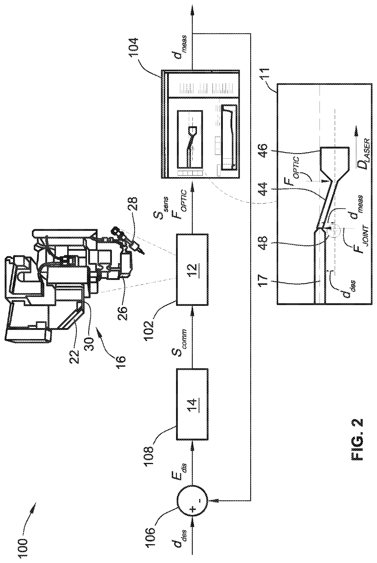
During the braze / weld process, the feed of filler wire tracks the joint seam; a resultant reaction force is applied by the joint to the wire, potentially pushing the wire out of alignment with the laser beam.

Method used


Image

  • Intelligent non-autogenous metalworking systems and control logic with automated wire-to-beam alignment
  • Intelligent non-autogenous metalworking systems and control logic with automated wire-to-beam alignment
  • Intelligent non-autogenous metalworking systems and control logic with automated wire-to-beam alignment

Examples


Embodiment Construction

[0016]This disclosure is susceptible of embodiment in many different forms. Representative embodiments of the disclosure are shown in the drawings and will herein be described in detail with the understanding that these embodiments are provided as an exemplification of the disclosed principles, not limitations of the broad aspects of the disclosure. To that extent, elements and limitations that are described, for example, in the Abstract, Introduction, Summary, and Detailed Description sections, but not explicitly set forth in the claims, should not be incorporated into the claims, singly or collectively, by implication, inference or otherwise. For purposes of the present detailed description, unless specifically disclaimed: the singular includes the plural and vice versa; the words “and” and “or” shall be both conjunctive and disjunctive; the words “any” and “all” shall both mean “any and all”; and the words “including,”“containing,”“comprising,”“having,” and the like, shall each m...


PUM

PropertyMeasurementUnit
threshold displacementaaaaaaaaaa

Abstract

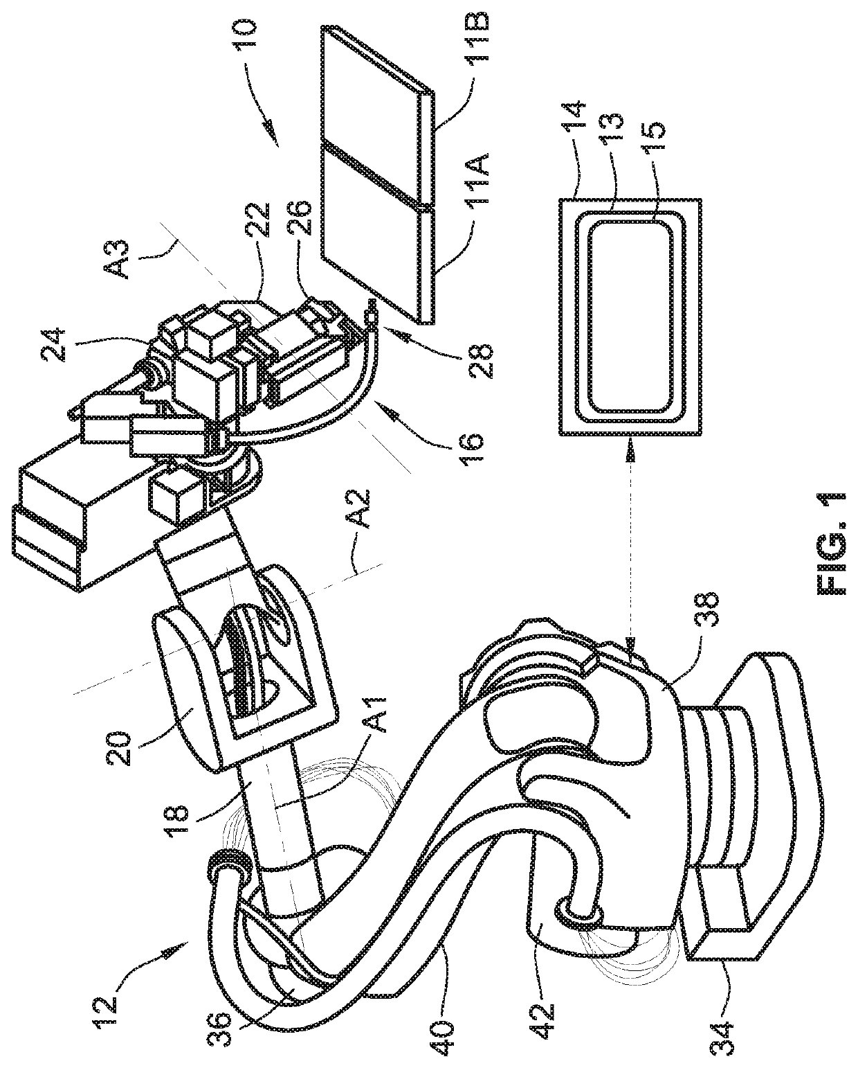
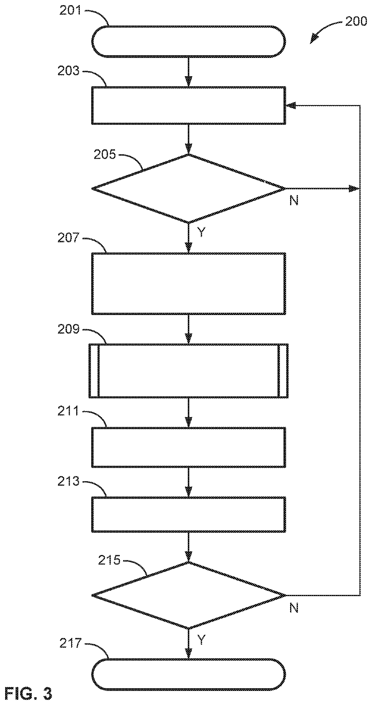
Presented are intelligent non-autogenous metalworking systems and control logic for automated wire-to-beam alignment, methods for making / using such systems, and robot-borne laser welding / brazing heads with closed-loop control for real-time wire alignment. A method for controlling operation of a non-autogenous workpiece processing system includes a system controller receiving sensor signals from a position sensor indicative of a location of filler wire discharged into a joint region by a wire feeder. Using the received sensor signals, the controller determines a displacement between the wire location and a location of a beam emitted onto the joint region by a beam emitter. If the wire displacement is greater than a threshold wire displacement value, the controller responsively determines a corrective force calculated to reduce wire displacement to below the threshold wire displacement value. The controller then commands the actuator to pivot the processing head to thereby apply the corrective force to the discharging filler wire.

Description

INTRODUCTION[0001]The present disclosure relates generally to metalworking techniques for joining or repairing workpieces. More specifically, aspects of this disclosure relate to systems, methods, and devices for automated wire-to-beam alignment in welding / brazing processes.[0002]Welding is a fabrication and repair process that bonds materials, usually metals or thermoplastics, by causing coalescence—the process by which two separate units or adjacent sections of a single unit grow together, fuse, or merge into a single body / section. In a joining operation, for example, two workpieces are juxtaposed oftentimes in abutting side-by-side relation, and then fused together by liquefying or plasticizing (softening without liquefying) the areas to be bonded together. Workpiece liquefaction / plasticization may be achieved through the application of heat, electric arc, electron beam, ultrasound, pressure, friction, or any combination thereof. For non-autogenous welding techniques, a filler ma...

Claims


Application Information

Patent Timeline
Patent Type & Authority Applications(United States)
IPC IPC(8): B23K26/08B23K26/211B23K1/005G05B19/418
CPCB23K26/0884B23K26/211G05B2219/49015G05B19/41875G05B2219/45138B23K1/0056B23K26/702B23K26/21G05B2219/45104
Inventor FORREST, JOHN
Owner GM GLOBAL TECH OPERATIONS LLC
Learn More