
Resettable bipolar switch sensor

Active Publication Date: 2021-04-08
MULTIDIMENSION TECH CO LTD
View PDF0 Cites 1 Cited by
  • Summary
  • Abstract
  • Description
  • Claims
  • Application Information

AI Technical Summary

Benefits of technology

The present invention is about a new switch sensor that has low power consumption, small size, and can be preset at the initial state. It includes a magnetoresistive sensing unit with a specific shape, insulating layer, and free layer. The laser programming process is used to protect the lower electrode layer from damage when the magnetoresistive sensing units are interconnected. The reset coil and reset wires are also included for a reliable resetting process. The invention has improved performance and accuracy compared to previous switch sensors.

Problems solved by technology

For the TMR linear switch magnetoresistive sensor bridge, a push magnetoresistive sensing unit chip with a single magnetic field sensing direction such as the X-axis is generally used and flipped by 180 degrees to obtain an X-axis pull magnetoresistive sensing unit chip, and then the two chips are connected by wire bonding, which has the advantage that the preparation method is simple, the chip only needs to correspond to a ferromagnetic reference layer structure, and the disadvantage that the two chips need to be operated for precise positioning in the same plane, thus increasing the possibility of loss of sensor measurement accuracy due to operating errors.
In addition, a GMR spin valve structure works in a CIP mode, that is, the operating current is parallel to the plane of a magnetic multilayer film, so that a change in the thickness of a free layer can cause a large change in the sensor resistance.
Therefore, the thickness change thereof is limited, so that Hc cannot be easily controlled.

Method used


Image

  • Resettable bipolar switch sensor
  • Resettable bipolar switch sensor
  • Resettable bipolar switch sensor

Examples


Embodiment Construction

[0044]In order to make the objectives, technical solutions, and advantages of the embodiments of the present invention clearer, the technical solutions in the embodiments of the present invention will be described clearly and completely below with reference to the accompanying drawings in the embodiments of the present invention. It is apparent that the described embodiments are a part of, not all, the embodiments of the present invention.

[0045]The present invention will be described in detail below with reference to the accompanying drawings and the embodiments.

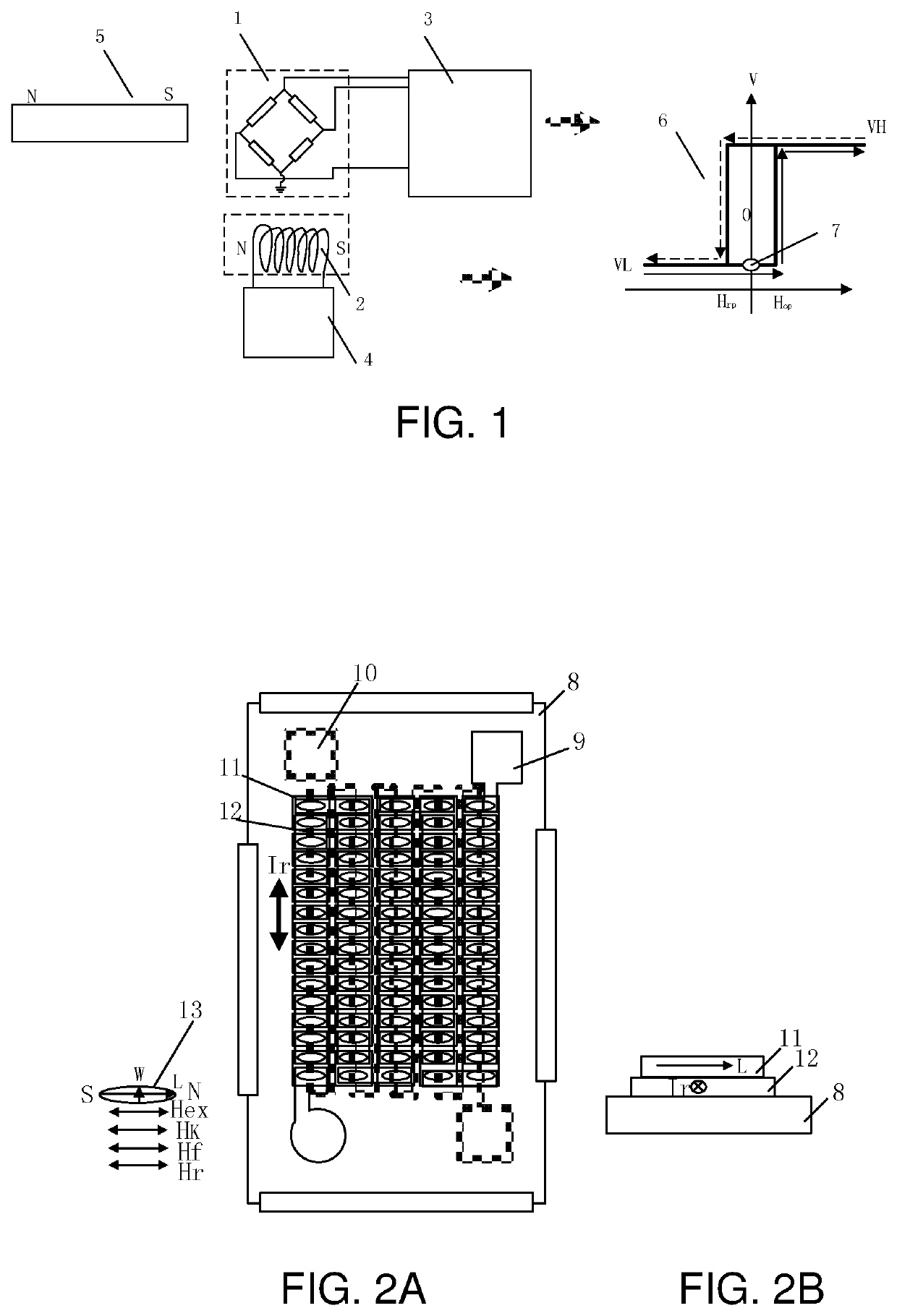
[0046]FIG. 1 is a working principle diagram of a resettable bipolar switch sensor, wherein 1 denotes a bipolar magnetic hysteresis switch sensor, 2 denotes a reset coil, 3 denotes an ASIC switch circuit, 4 denotes a reset circuit, and 5 denotes an external magnetic field. In this example, it is a square hard magnet with a N magnetic pole and an S magnetic pole. For convenience, an external magnetic field Hex is specified in ...


PUM


Abstract

A resettable bipolar switch sensor is disclosed which comprises a bipolar magnetic hysteresis switch sensor, a reset coil, an ASIC switch circuit and a power reset circuit. The bipolar magnetic hysteresis switch sensor comprises a substrate and a magnetoresistive sensing arm located on the substrate. The magnetoresistive sensing arm is of a two-port structure composed of one or more magnetoresistive sensing unit strings arranged in series, parallel, or series-parallel. The magnetization direction of a free layer of a TMR magnetoresistive sensing unit is determined by an anisotropy field Hk, and together with the magnetization direction of a reference layer and the applied magnetic field, it can orient in an N or S direction. The reset coil is located between the substrate along with the magnetoresistive sensing unit, or it is located on a lead frame below the substrate. The direction of the reset magnetic field is either N or S. The ASIC switch circuit comprises a biasing circuit module, a reading circuit module, and an output circuit module. The power reset circuit is connected to the reset coil. This device has the advantages of low power consumption and small size in addition to the capability to set initial state of the switch sensor.

Description

TECHNICAL FIELD[0001]The present invention relates to the field of magnetic sensors, and in particular, to a resettable bipolar switch sensor.BACKGROUND[0002]Magnetoresistive switch sensors are widely used in fields such as consumer electronics, home appliances, utility meters (electric meters, water meters, and gas meters), automobiles, and various industrial applications. Typical mainstream magnetic switch sensors include Hall sensors and anisotropic magnetoresistance (AMR) sensors. In the fields of consumer electronics and utility-meter applications, the power consumption of Hall switch sensors and AMR switch sensors can reach microamperes. This is obtained at the expense of their operating frequency, which is tens of Hertz. The switching point for these switch sensors is dozens of Gauss. In automobiles, industrial applications, and in environments where high operating frequency is required, the power consumption of Hall switch sensors and AMR switch sensors is in the milliampere...

Claims


Application Information

Patent Timeline
IPC IPC(8): G01R33/09
CPCG01R33/098G01R33/093G01R33/0052G01R33/0058G01R33/0088G01R33/0017H03K17/80
Inventor DEAK, JAMES GEZAZHOU, ZHIMIN
Owner MULTIDIMENSION TECH CO LTD
Learn More