
Hard carbon film, manufacturing method for same, and sliding member

a manufacturing method and technology of hard carbon film, applied in the direction of vacuum evaporation coating, mechanical equipment, transportation and packaging, etc., can solve the problems of reducing the hardness of the film, affecting the hard carbon film itself and its counterpart materials, and affecting the hard carbon film. , to achieve the effect of reducing the occurrence of cost increases as well as time and effort, excellent wear resistance, and low abrasiveness

Pending Publication Date: 2021-05-27
NIPPON ITF
View PDF4 Cites 1 Cited by
  • Summary
  • Abstract
  • Description
  • Claims
  • Application Information

AI Technical Summary

Benefits of technology

The present patent provides a way to make a hard carbon film that is highly resistant to wear and has low abrasion. This is done by smoothing the surface of the film while inhibiting the formation of costly and time-consuming lapping treatments. Oil containing MoDTC can be used to achieve this.

Problems solved by technology

It is known that, in a case where a hard carbon film produced by using a CVD method in which a hydrocarbon gas serves as a film forming source is used, if the hard carbon film is used in an oil containing MoDTC as described above, a reaction product MoO3 is produced on a film surface and abnormal wear occurs while the friction coefficient is lowered since the hard carbon film is a hydrogen-containing hard carbon film.
Therefore, although abnormal wear can be suppressed by adding metal atoms to the film, there is concern of hardness of the film decreasing in that case.
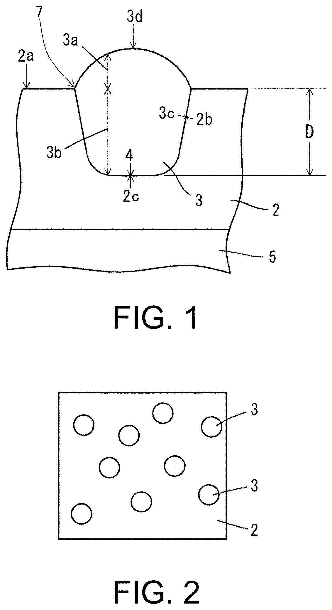
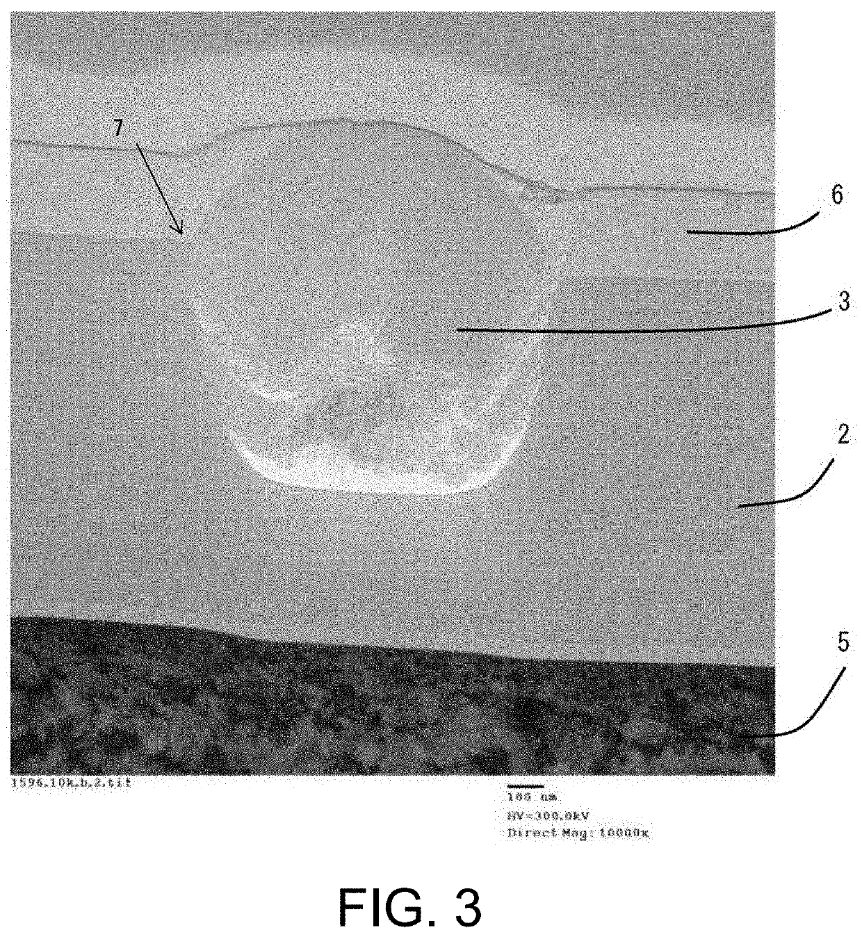
The protruding shaped parts have a hardness equivalent to that of the hard carbon film, harm the hard carbon film itself and counterpart materials when they fall off during sliding, and particularly exhibit apparent aggressiveness to a counterpart material when a soft material such as aluminum or copper is used as a counterpart material.
For those reasons, when a hydrogen-free hard carbon film is applied to a sliding member, removal of protruding shaped parts through a lapping treatment or the like is essential, which is a cause of cost increase.
In addition, since the protruding shaped parts strongly bond to the hard carbon film, it is difficult to completely remove the parts even if a lapping treatment or the like is performed.
However, a hydrogen-free hard carbon film produced using the arc vaporization method has a micro-convex structure on the sliding surface that is difficult to smoothen since the film has high hardness and the protruding shaped parts are not completely removed.

Method used


Image

  • Hard carbon film, manufacturing method for same, and sliding member
  • Hard carbon film, manufacturing method for same, and sliding member
  • Hard carbon film, manufacturing method for same, and sliding member

Examples


example 1-1

(1) Example 1-1

[0136]A hard carbon film having a thickness of 1.0 μm was deposited by using a carburized disc (31 mm in diameter (φ)×3 mm in thickness (t), HRC 60, and surface roughness Ra<0.01 μm) formed of SCM 415 as a base material, and introducing a gas containing hydrogen atoms onto the base material using arc vapor deposition.

[0137]Specifically, first, the base material with the surface from which dirt and an oxide layer had been removed beforehand was set in a jig inside a deposition apparatus, and a Cr film having a thickness of 50 nm was formed as an intermediate layer on the deposition target surface using an arc ion plating method using Cr as an arc vaporization source.

[0138]Next, while vaporizing a graphite cathode through arc discharge, Ar gas and methane gas were introduced from outside, and a hard carbon film having a thickness of 1.0 μm was deposited on the base material. Further, at this time, by rotating the jig on which the base material was set, deposition is per...

example 1-2

(2) Example 1-2

[0139]A hard carbon film having a thickness of 1.0 μm was first deposited on a base material on which an intermediate layer had been formed likewise similarly to Example 1-1. Then, Ar gas and acetylene gas were introduced into the same deposition apparatus, self-discharge CVD discharge was generated by applying a bias voltage of 600 V thereto at a gas pressure of 3.0 Pa, and thereby a low-hardness carbon film having a thickness of 0.3 μm was deposited and coated on the hard carbon film.

(3) Comparative Example 1-1

[0140]A hard carbon film having a thickness of 1.0 μm was deposited on the same base material using conventional vacuum arc vapor deposition in which no gas is introduced. Specifically, the hard carbon film was deposited on the base material on which an intermediate layer had been formed as in Example 1-1 and Example 1-2 by introducing only Ar gas from outside while vaporizing a graphite cathode through arc discharge.

[0141]2. Evaluation of Film Characteristics...


PUM

PropertyMeasurementUnit
depthaaaaaaaaaa
thicknessaaaaaaaaaa
thicknessaaaaaaaaaa

Abstract

A hard carbon film that forms a sliding surface of a sliding member, wherein the hard carbon film includes terminal atoms that bond to carbon atoms and has a plurality of protruding shaped parts, part of which protrude from the surface thereof, with the periphery of each of the plurality of protruding shaped parts being terminated by a terminal atom. A manufacturing method for the hard carbon film for producing the hard carbon film on a sliding surface of the sliding member using arc vapor deposition having graphite as the vaporization source, wherein a gas containing the terminal atoms that bond to carbon atoms is introduced, and the plurality of protruding shaped parts is grown on the surface of the hard carbon film while terminating the periphery of the plurality of protruding shaped parts by bonding of the terminal atoms to carbon atoms.

Description

TECHNICAL FIELD[0001]The present disclosure relates to a hard carbon film, a manufacturing method for the same, and a sliding member, and more specifically, a hard carbon film that exhibits excellent low abrasiveness while maintaining high wear resistance in oil containing a friction modifier, a manufacturing method for the same, and a sliding member.BACKGROUND ART[0002]Recently, providing a diamond-like carbon (DLC) film having excellent characteristics for sliding materials such as low abrasiveness, high wear resistance, and low adhesion (seizure resistance) on a sliding surface of a sliding member has been proposed and widely applied to sliding members of automobile parts and the like.[0003]Meanwhile, among lubricants in which sliding members are used, oils containing a friction modifier such as sulfurized molybdenum dialkyldithiocarbamate (MoDTC) are used, and a technique for sliding pistons on which hard carbon films are formed and the like in such a friction modifier-containin...

Claims


Application Information

Patent Timeline
Patent Type & Authority Applications(United States)
IPC IPC(8): C23C14/06C23C14/32C23C14/24C23C16/26F16C33/10
CPCC23C14/0605C23C14/325F16C33/1025C23C16/26C23C14/243F16C33/043C23C14/0021C23C14/5886C23C14/0611Y10T428/30
Inventor OOSHIRO, TAKEHIKOFUKUTANI, YUKAKOMIYAKE, KOJI
Owner NIPPON ITF
Learn More