Method of manufacturing a height-modulated optical diffractive grating

a technology of optical diffractive grating and manufacturing method, which is applied in the field of manufacturing optical diffractive gratings, can solve the problems of high cost, high cost, and difficult fabrication of micro- and nanostructures with varying heights on the same substrate, and achieve the effect of convenient combining height and fill factor modulation

Active Publication Date: 2021-05-27
DISPELIX OY
View PDF0 Cites 1 Cited by
  • Summary
  • Abstract
  • Description
  • Claims
  • Application Information

AI Technical Summary

Benefits of technology

The invention aims to offer a new method for producing optically diffractive gratings that have modulations in their height and fill factor. The method is designed to require less process steps, and in particular, does not require high lateral precision processing. Additionally, the method allows for easy combination of height and fill factor modulation.

Problems solved by technology

Moreover, in some cases non-polymeric materials are needed, which adds process complexity in comparison with direct polymer modulation.
In particular, fabrication of micro- and nanostructures with varying heights on a same substrate is difficult especially in the case of inorganic materials that are difficult to process.
This also requires highly optimized and often complicated processing of the material.
Because of the complexity of the method, the yield of this process is low.
Moreover, overlay exposure requires lateral placement accuracy in nanometer level, and any deviations from optimal causes losses in optical performance.

Method used


Image

  • Method of manufacturing a height-modulated optical diffractive grating
  • Method of manufacturing a height-modulated optical diffractive grating

Examples


Embodiment Construction

Definitions

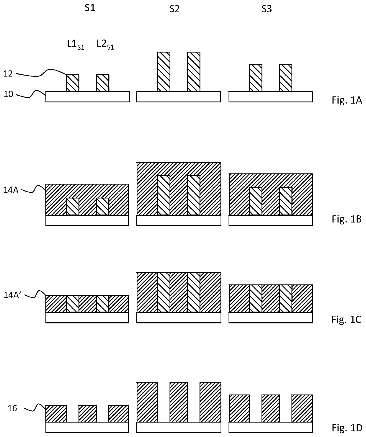
[0030]The term “element” herein means any solid micro- or nanoscale feature rising above the substrate surface and capable of serving, when arranged in a periodic structure, as an elementary block of a diffractive pattern or its intermediate product. A “temporary element” or “sacrificial element” is an element, which is at least partly removed during the process.

[0031]The term “line element” or “line” herein refers to an elongated element forming, or used as an intermediate feature to form, the present pattern. Typically, in a diffractive pattern for display applications, a line is a straight ridge having a desired cross-sectional general shape, such as a rectangular or triangular shape. Line elements are typically used in one-dimensional gratings (linear gratings).

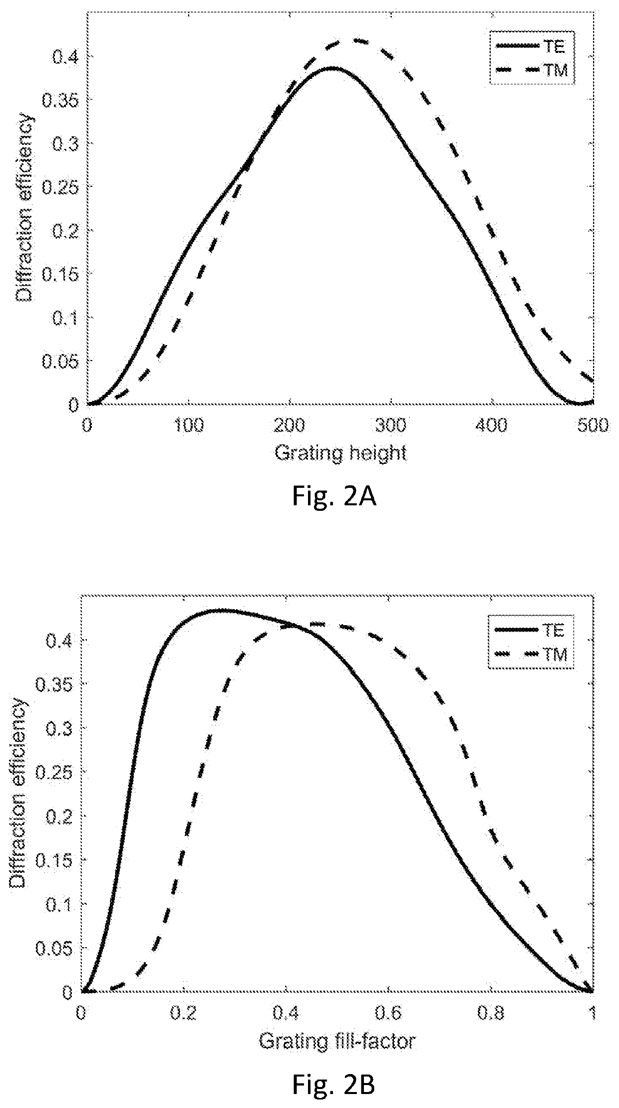
[0032]The term “fill factor” refers to the proportion of grating structure material to surrounding material (e.g. air or other solid material) within a grating period. In the typical case of rectangular grating...


PUM

PropertyMeasurementUnit
transmittanceaaaaaaaaaa
areaaaaaaaaaaa

Abstract

The invention concerns a method of manufacturing a height-modulated optically diffractive grating. The method comprises providing a substrate and manufacturing a plurality of temporary elements of first material onto the substrate, the elements being separated by gaps and arranged as a periodic structure comprising at least two periods having different element heights. A coating layer of second material is deposited on the plurality of temporary elements such that the coating layer fills said gaps and covers said temporary elements. Then, a uniform layer of the second material is removed in order to expose said temporary elements and the first material is removed in order to form a height modulated pattern of the second material onto the substrate as the optically diffractive grating. The invention relaxes manufacturing constraints when manufacturing gratings with locally varying diffraction efficiency.

Description

FIELD OF THE INVENTION[0001]The invention relates to manufacturing of micro- and nanostructures for optical purposes. In particular, the invention relates to manufacturing optically diffractive gratings, which can be used for example in display applications, such as near-to-eye displays.BACKGROUND OF THE INVENTION[0002]Near-to-eye displays (NEDs) and head-up displays (HUDs) typically involve diffractive gratings to produce a viewable image. Gratings are needed as in-coupling gratings, which couple an image from an image source to a wave guide, as out-coupling gratings, which produce the final viewable image for the user, and as exit pupil expanders (EPEs), which increase the size of the displays exit pupil.[0003]The quality and characteristics of the gratings determine the quality of resulting image. In addition to having distinct and consistent grating lines, in advanced applications it is desirable to be able to control the diffraction efficiency of the grating locally. This can b...

Claims


Application Information

Patent Timeline
Patent Type & Authority Applications(United States)
IPC IPC(8): G02B27/01G02B5/18G02B27/09G02B27/00G02B27/42
CPCG02B27/0101G02B5/1847G02B27/4233G02B27/0081G02B27/0944C23C16/01G02B5/1857H01L21/02C23C16/045C23C16/345C23C16/405B29D11/00769G02B2027/0125G02B27/0172G02B5/1861G02B5/1866
Inventor VARTIAINEN, ISMORAHOMÄKI, JUSSIERDMANIS, MIKHAIL
Owner DISPELIX OY
Why Eureka
Try Eureka