Gas separation method and gas separator

a gas separator and gas separation technology, applied in the direction of separation process, dispersed particle separation, chemistry apparatus and processes, etc., can solve the problems of difficult to increase the concentration of cosub>2 /sub>, difficult to continue stable separation, and easy to deteriorate separation capabilities, etc., to improve the selectivity of carbon dioxid

Pending Publication Date: 2021-07-01
NGK INSULATORS LTD
View PDF3 Cites 1 Cited by
  • Summary
  • Abstract
  • Description
  • Claims
  • Application Information

AI Technical Summary

Benefits of technology

[0009]The present invention is directed to a gas separation method of separating carbon dioxide in a mixed gas, and it is an object of the present invention to improve the carbon dioxide selectivity in a separation membrane in order to increase the concentration of carbon dioxide in a gas that has permeated through the separation membrane.
[0010]A gas separation method according to a preferable embodiment of the present invention includes a) preparing a separation membrane complex in which a separation membrane with pores having a mean pore diameter less than or equal to 1 nm is formed on a porous support, and b) supplying a mixed gas that includes carbon dioxide and another gas from a side of the separation membrane to the separation membrane complex and obtaining a permeated gas by causing the carbon dioxide in the mixed gas to permeate through the separation membrane and the support. The operation b) is performed in a state in which at least part of a permeation surface of the support, from which the permeated gas is exhausted has a temperature lower by 10° C. or more than a temperature of the mixed gas before being supplied to the separation membrane complex. This gas separation method improves the carbon dioxide selectivity in a separation membrane.
[0019]The present invention is also directed to a gas separator for separating carbon dioxide in a mixed gas. A gas separator according to a preferable embodiment of the present invention includes a separation membrane complex in which a separation membrane with pores having a mean pore diameter less than or equal to 1 nm is formed on a porous support, and a gas supply part that supplies a mixed gas including carbon dioxide and another gas from a side of the separation membrane to the separation membrane complex. The carbon dioxide in the mixed gas is caused to permeate through the separation membrane and the support and is separated from the mixed gas in a state in which at least part of a permeation surface of the support, from which a gas having permeated through the separation membrane is exhausted, has a temperature lower by 10° C. or more than a temperature of the mixed gas before being supplied to the separation membrane complex. This gas separator improves the carbon dioxide selectivity in a separation membrane.

Problems solved by technology

Incidentally, in the case where CO2 is separated and collected from a combustion exhaust gas with use of a zeolite membrane such as described in Documents 1 and 2, it is difficult to increase the concentration of CO2 in a gas that has permeated through the zeolite membrane because CO2 in the combustion exhaust gas has a relatively low partial pressure.
With a non-porous facilitated transport membrane such as described in Document 3, it is difficult to continue stable separation for a long period of time because separation capabilities easily deteriorate with decreasing amount of moisture in the facilitated transport membrane.
However, since the permeability of the carbon dioxide separation membranes to carbon dioxide decreases with a drop in temperature, it is hard to think of cooling each carbon dioxide separation membrane (i.e., a single carbon dioxide separation membrane) so as to have a lower temperature than the temperature of a gas supplied to this separation membrane.
Thus, it is difficult to use this porous membrane for the separation of CO2.

Method used


Image

  • Gas separation method and gas separator
  • Gas separation method and gas separator

Examples


Embodiment Construction

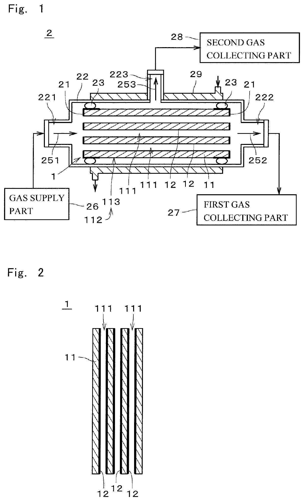
[0024]FIG. 1 is a diagram illustrating a schematic structure of a gas separator 2 according to one embodiment of the present invention. In FIG. 1, cross-hatching in the sections of some components is omitted. The gas separator 2 is an apparatus that separates carbon dioxide (CO2) from a mixed gas that includes carbon dioxide and other gases. For example, the mixed gas is a combustion exhaust gas emitted from a thermal power station.

[0025]The gas separator2 includes a separation membrane complex 1, sealers 21, an outer cylinder 22, two seal members 23, and a gas supply part 26, a first gas collecting part 27, a second gas collecting part 28, and a cooler 29. The separation membrane complex 1, the sealers 21, and the seal members 23 are placed in the internal space of the outer cylinder 22. The gas supply part 26, the first gas collecting part 27, and the second gas collecting part 28 are disposed outside the outer cylinder 22 and connected to the outer cylinder 22. In the example ill...


PUM


Abstract

A gas separator includes a separation membrane complex in which a separation membrane with pores having a mean pore diameter less than or equal to 1 nm is formed on a porous support, and a gas supply part that supplies a mixed gas including CO2 and another gas from the side of the separation membrane to the separation membrane complex. Then, CO2 in the mixed gas is caused to permeate through the separation membrane and the support and is separated from the mixed gas in a state in which at least part of a permeation surface of the support, from which a gas having permeated through the separation membrane is exhausted, has a temperature lower by 10° C. or more than the temperature of the mixed gas before being supplied to the separation membrane complex.

Description

CROSS-REFERENCE TO RELATED APPLICATION[0001]This present application is a continuation application of International Application No. PCT / JP2019 / 036386, filed on Sep. 17, 2019. The contents of this application are incorporated herein by reference in their entirety.TECHNICAL FIELD[0002]The present invention relates to a gas separation method and a gas separator.BACKGROUND ART[0003]The separation of gases such as carbon dioxide (CO2) from a combustion exhaust gas emitted from a thermal power station or other such installation has conventionally been performed. For example, Japanese Patent Application Laid-Open No. 2003-159518 (Document 1) and Japanese Patent Application Laid-Open No. 2015-044162 (Document 2) propose techniques for separating CO2 from a mixed gas with use of a zeolite membrane. International Publication WO / 2009 / 093666 (Document 3) proposes a technique for separating CO2 with use of a facilitated transport membrane.[0004]Japanese Patent Application Laid-Open No. 2017-1541...

Claims


Application Information

Patent Timeline
Patent Type & Authority Applications(United States)
IPC IPC(8): B01D53/22B01D71/02
CPCB01D53/228B01D2053/222B01D71/024C01B32/50Y02C20/40B01D71/028B01D2256/22B01D2257/502B01D2257/11B01D2257/102B01D2257/404B01D2257/104B01D2257/108B01D2257/406B01D2257/302B01D2257/304B01D2257/602B01D2257/60B01D2257/408B01D2257/308B01D2257/702B01D2257/306B01D2257/708B01D2257/204B01D2257/7022
Inventor NODA, KENICHIYAJIMA, KENJISHIMIZU, KATSUYA
Owner NGK INSULATORS LTD
Why Eureka
Try Eureka