
Steel belt conveying apparatus for transporting and bolting machine and transporting and bolting machine

a conveying apparatus and bolting machine technology, applied in the direction of conveyor parts, mining structures, earthwork drilling and mining, etc., can solve the problems of high labor intensity, low working efficiency, and difficulty in implementing the mechanization of steel belt construction, so as to reduce the labor intensity of steel belt installation, reduce manual handling, lifting and mounting, and increase the mechanization level and safety of anchor bolt support and protection

Active Publication Date: 2021-07-01
CHINA UNIV OF MINING & TECH
View PDF0 Cites 9 Cited by
  • Summary
  • Abstract
  • Description
  • Claims
  • Application Information

AI Technical Summary

Benefits of technology

The present invention provides a steel belt conveying apparatus for a transporting and bolting machine. The apparatus uses a chain structure to transport a steel belt to a position of a roadway roof to be constructed, reducing manual handling, labor intensity, and installation time. The apparatus includes an upper horizontal conveying portion, an inclined conveying portion, and a lower horizontal conveying portion, with a steel belt for roof support and protection placed on the lower horizontal conveying portion and driven by a chain of the lower horizontal conveying portion to move to the upper horizontal conveying portion. The upper and lower horizontal conveying portions are adjusted to move forwards and backwards to convey the steel belt to a required position, and then the steel belt is supported and protected. The apparatus also includes chain tensioning apparatus to prevent chain loosening, an upper horizontal L-shaped limiting plate to prevent the steel belt from being transported forward excessively and falling causing personal injury, and a connecting rod frame to adapt to different roadway heights. The apparatus is installed on the transporting and bolting machine to facilitate coordination working of the jumbolter and the steel belt conveying apparatus. Overall, the apparatus reduces labor intensity, improves mechanization level, and safety of support and protection of anchor bolt.

Problems solved by technology

Mechanization of construction of steel belts has always been difficult to implement.
In most cases, the steel belts are manually handled, lifted, and mounted, leading to problems such as high labor intensity and low working efficiency.
This is one of constraints of mechanization, automation, and intelligence in tunneling.

Method used


Image

  • Steel belt conveying apparatus for transporting and bolting machine and transporting and bolting machine
  • Steel belt conveying apparatus for transporting and bolting machine and transporting and bolting machine
  • Steel belt conveying apparatus for transporting and bolting machine and transporting and bolting machine

Examples


Embodiment Construction

[0047]Specific implementations of the present invention are further described below based on FIG. 1 to FIG. 25.

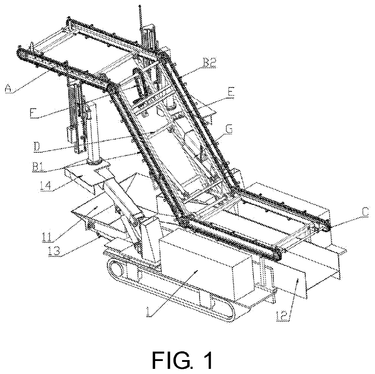
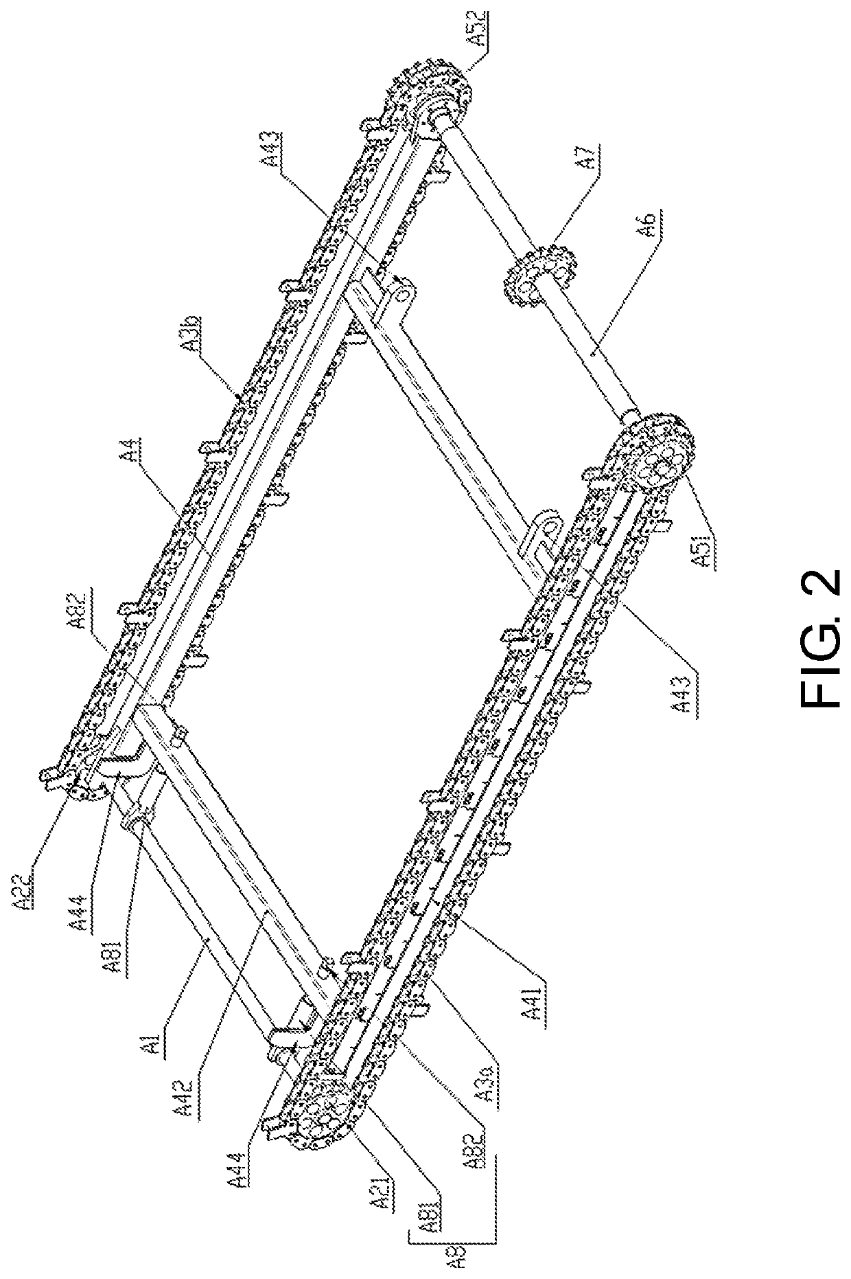
[0048]Referring to FIG. 1, an embodiment provides a steel belt conveying apparatus for a transporting and bolting machine. The steel belt conveying apparatus includes an upper horizontal conveying portion A, a left inclined conveying chain B1, a right inclined conveying chain B2 (the left inclined conveying chain B1 and the right inclined conveying chain B2 belong to an inclined conveying portion), a lower horizontal conveying portion C, a connecting rod frame D, an inclined frame E, a drive portion F, and a height adjustment cylinder G. Referring to FIG. 2, the upper horizontal conveying portion A specifically includes an upper horizontal direction changing shaft A1, an upper horizontal left direction changing wheel A21, an upper horizontal right direction changing wheel A22, an upper horizontal left chain A3a, an upper horizontal right chain A3b, an upper horizontal frame...


PUM


Abstract

A steel belt conveying apparatus includes upper and lower horizontal conveying portions, left and right inclined conveying chains, a connecting rod frame, an inclined frame, a drive portion, and a height adjustment cylinder. The left inclined conveying chain is separately connected to the upper and lower horizontal conveying portions. The right inclined conveying chain is separately connected to the upper and lower horizontal conveying portions. A top portion of the connecting rod frame is hingedly connected to an upper horizontal frame of the upper horizontal conveying portion. A bottom portion is hingedly connected to a lower frame of the lower horizontal conveying portion. A top portion of the inclined frame is hingedly connected to an upper horizontal drive shaft of the upper horizontal conveying portion, and a bottom portion is hingedly connected to a lower horizontal drive shaft of the lower horizontal conveying portion.

Description

BACKGROUNDTechnical Field[0001]The present invention relates to a transporting and bolting machine, and specifically, to a steel belt conveying apparatus for a transporting and bolting machine and a transporting and bolting machine, which is particularly suitable for roadway tunneling with simple geological conditions, a small coal seam inclination angle, and good roof stability.Description of Related Art[0002]Anchor bolt support and protection has many advantages such as safety, flexibility, and high efficiency, and is a support and protection method widely applied in coal mine roadways in China. Steel belts are important components in anchor bolt support and protection systems, and play a key role in improving overall effects of support and protection of anchor bolts and maintaining the integrity of surrounding rocks. The roles are mainly reflected in the following aspects. Pre-stressing force and working resistance diffusion of the anchor bolts, supporting and protecting a surfac...

Claims


Application Information

Patent Timeline
Patent Type & Authority Applications(United States)
IPC IPC(8): B65G15/48B65G41/00
CPCB65G15/48B65G41/006E21D20/00E21F13/006B65G15/44B65G15/50B65G17/12
Inventor ZHANG, NONGXIE, ZHENGZHENGZHOU, JUNYAOWEI, QUN
Owner CHINA UNIV OF MINING & TECH
Learn More