A pulsed flow reactor and use thereof

a flow reactor and pulse technology, applied in chemical/physical/physico-chemical processes, chemical apparatus and processes, transportation and packaging, etc., can solve the problems of difficult scaling up, deterioration of process control, and inability to design and implement suitable reactors for every specific process, so as to improve the scalability of flow reactors naturally and improve the effect of scalability

Active Publication Date: 2021-07-08
AJINOMOTO OMNICHEM SA +1
View PDF0 Cites 1 Cited by
  • Summary
  • Abstract
  • Description
  • Claims
  • Application Information

AI Technical Summary

Benefits of technology

[0017]It is an object of the present invention to provide a flow reactor having improved scalability.

Problems solved by technology

However, on laboratory and pilot scale, it is impractical and expensive to design and implement a suitable reactor for every specific process.
Most of these laboratory reactors utilize (coiled) tubing, narrow channels or falling films of which it is known that these are difficult to scale-up.
Specifically, increasing the internal volume by increasing the tube diameter or the channel cross-section results in a deteriorated process control, i.e. mass transfer, heat exchange and / or flow hydrodynamics become more difficult to control.
Furthermore, increasing the tube or channel length increases the pressure drop over the length of the reactor.
However, this has the disadvantage that different fluids typically have a different viscosity which affects the extent of the laminar boundary layer flows generated by a specific shape of static mixing element.
As the mixing elements are an integral part of the flow reactor, such a replacement is not possible.
Furthermore, it may even be that an entirely new shape needs to be designed for a specific fluid, which may require extensive modelling and / or simulations.
Although an effective mixing can be achieved in this way, this has the disadvantage that the flow reactor needs to be sufficiently long for the fluid to have the desired residence time.
Therefore, the serpentine reactors may be placed in series with the different plates of the reactor being stacked onto one another thereby creating the required length, but, as also disclosed in WO-A-2012 / 025224, the longer the process channel, the higher the pressure drop becomes, which is undesirable and in many cases exceed the pressure limit of the reactor or auxiliaries like pumps.
Moreover, an already quite long laboratory reactor takes away the option of scaling-up by placing multiple reactors in series as the pressure drop cannot be controlled sufficiently to have a narrow RTD.
Another downside of the serpentine flow reactor disclosed in WO-A-2012 / 025224 is that the static mixing elements create very narrow fluid passages between them, typically having a dimension in the sub-millimetre range, i.e. the static mixing elements form micro-fluidic channels.
Such small channels provide only a limited useable reactor volume (e.g. according to the disclosure in WO-A-2012 / 025224 the mixing elements take up between 40% and 60% of the total process channel volume) which naturally limits production capacity per channel.
While WO-A-2012 / 025224 discloses that multiple serpentine flow reactors may be placed in parallel to scale-up the production capacity, the low volume of the micro-fluidic channels effectively reduces the production capacity by such an amount that the number of flow reactors needed for actual production becomes high, which leads to issues in process control, i.e. it becomes very difficult to monitor and control the process parameters in the various parallel flow reactors which may lead to quality differences between the product streams of the various parallel reactors.
A downside of these flow reactors is that the small volume of the process channel is problematic for high-throughput.
Moreover, the single microchannel that forms the process channel may easily get blocked due to clogging, which blockage may lead to a failure of the flow reactor.
In addition, employing solids (e.g. catalysts, reagents, etc.) is difficult in single process channels in the sub-millimetre range.
Another disadvantage of the serpentine flow reactors is that the channel volume and thus also the surface per plate is limited to less than 50% and in many cases to less than 10%.
Another disadvantage of the serpentine flow reactors is that they cannot easily be scaled up by increasing the cross-sectional size of the process channel since such a scale-up generates a different hydrodynamic behavior, especially as a result of the curves.
As a result, in order to obtain the same residence time for the reaction, the flow rate has to be increased, thus affecting the hydrodynamic behavior of the flow.
However, as already described above, it is not easy to scale-up such a tubular process channel.
In particular, increasing the diameter results in a deteriorated process control, while increasing the channel length also increases the pressure drop.
Upscaling the flow reactor disclosed in WO-A-2017 / 175207 is not straightforward for several reasons.
First, as described above, the serpentine layout of the process channel means that upscaling the reactor will increase its length.
As such, in order to obtain the same residence time for the reaction, the flow rate has to be increased, thus affecting the hydrodynamic behavior of the flow.
Second, varying the cross-section of the process channel (e.g. increasing the width) results, as for a tubular process channel, in a deteriorated process control.
Moreover, varying the cross-section of the process channel may also lead to changes in the baffle shape and / or periodicity.

Method used


Image

  • A pulsed flow reactor and use thereof
  • A pulsed flow reactor and use thereof
  • A pulsed flow reactor and use thereof

Examples


Embodiment Construction

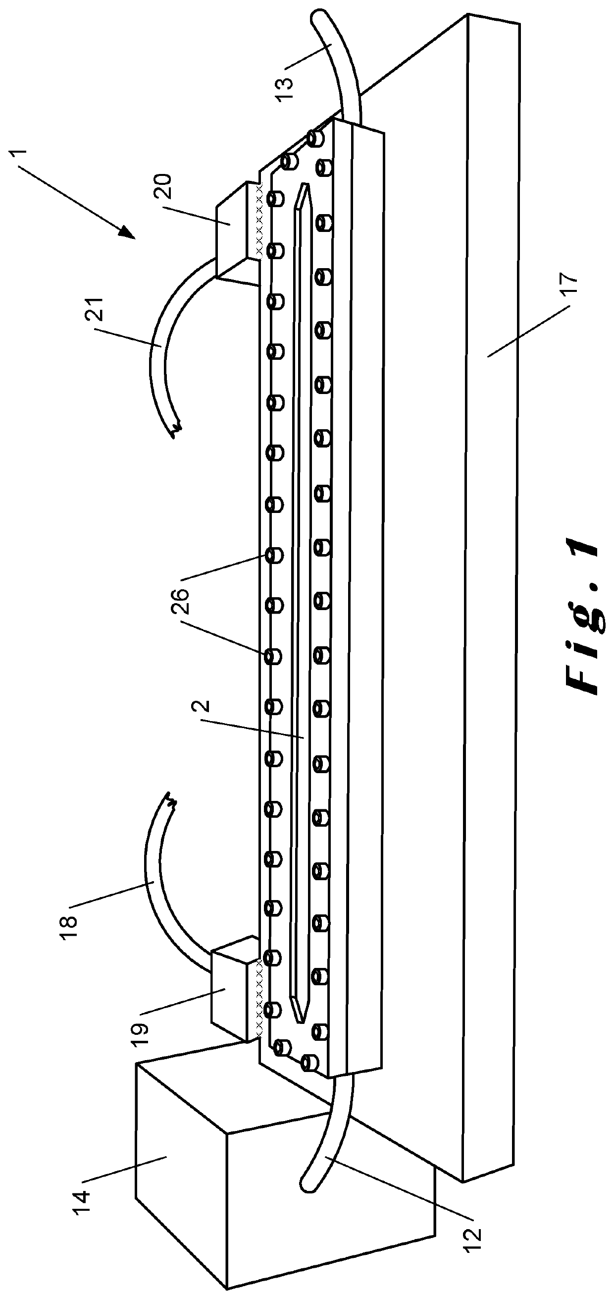
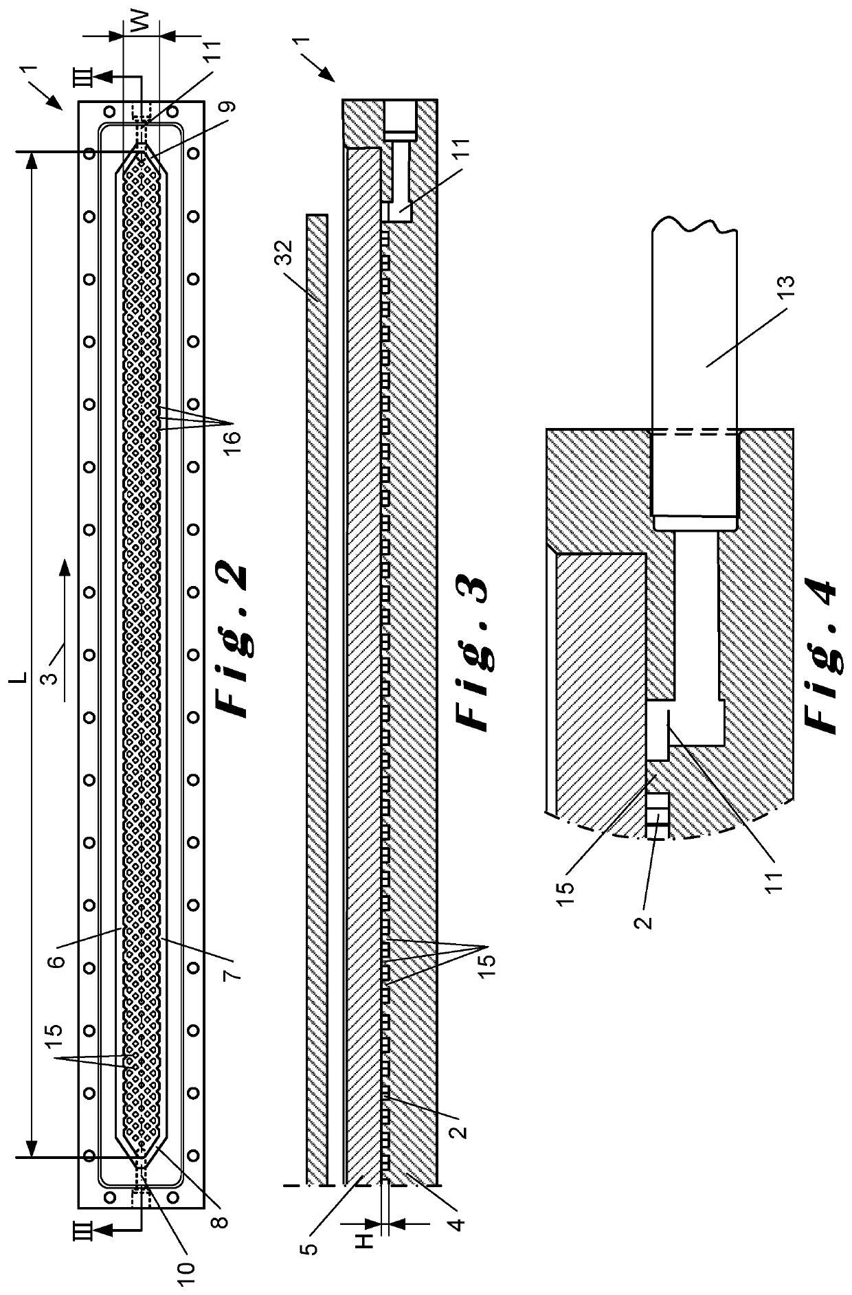
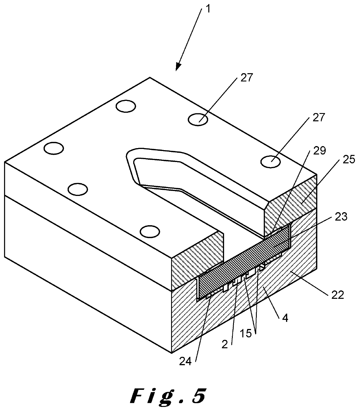
[0068]The present invention will be described with respect to particular embodiments and with reference to certain drawings but the invention is not limited thereto but only by the claims. The drawings described are only schematic and are non-limiting. In the drawings, the size of some of the elements may be exaggerated and not drawn on scale for illustrative purposes. The dimensions and the relative dimensions do not necessarily correspond to actual reductions to practice of the invention.

[0069]Furthermore, the terms first, second, third and the like in the description and in the claims, are used for distinguishing between similar elements and not necessarily for describing a sequential or chronological order. The terms are interchangeable under appropriate circumstances and the embodiments of the invention can operate in other sequences than described or illustrated herein.

[0070]Moreover, the terms top, bottom, over, under and the like in the description and the claims are used fo...


PUM

PropertyMeasurementUnit
oscillation frequencyaaaaaaaaaa
distanceaaaaaaaaaa

Abstract

A planar flow reactor includes a straight planar process channel, a flow generator, and a plurality of static mixing elements disposed within the process channel. The flow generator is configured to generate a pulsatile flow within the process channel, and the static mixing elements are configured to locally split and recombine the flow. The straight planar process channel enables the generation of a flow pattern that is largely independent of the width of the process channel, meaning that the throughput may be increased by increasing the width without significantly affecting the residence time distribution or the flow behavior. Furthermore, by creating a pulsatile flow within the process channel, turbulence and / or chaotic fluid flows may be generated even at low net flow rates, i.e. low net Reynolds numbers.

Description

TECHNICAL FIELD[0001]The present invention relates to a planar flow reactor and in particular to a flow reactor suitable for multiphasic reactions and / or photochemical processes. The present invention also relates to a use of the flow reactor to produce a product stream and to a method for producing a product stream using the flow reactor.BACKGROUND ART[0002]Continuous manufacturing is often the most cost-effective and efficient way to produce goods. This technology was originally developed for the production of very high volumes of end products, for example in the petroleum and food industries. However, in recent times, continuous manufacturing has also been used for low volume production, for example in the chemical and pharmaceutical industries, as other benefits (e.g. safety, quality, mass and heat transfer, etc.) became apparent. Especially in the pharmaceutical industry, regulatory agencies (e.g. the FDA) prefer a switch from batch to continuous processing of active pharmaceut...

Claims


Application Information

Patent Timeline
Patent Type & Authority Applications(United States)
IPC IPC(8): B01J19/00B01J19/24B01F23/00
CPCB01J19/0093B01J2219/00934B01J19/241B01J2219/00074B01J2219/00164B01J2219/00768B01J2219/00777B01J2219/00783B01J2219/00831B01J2219/00833B01J2219/00837B01J2219/0086B01J2219/00873B01J2219/00889B01J2219/00894B01J2219/009B01J2219/00907B01J19/006
Inventor METTEN, BERT D FTOYE, KOENVAN AKEN, KOEN JEANNE ALFONSDEBROUWER, WOUTER
Owner AJINOMOTO OMNICHEM SA
Why Eureka
Try Eureka