Microfluidic chip and microfluidic device for physicochemically treating single cell, and method for physicochemically treating single cell by using microfluidic chip and microfluidic device
a microfluidic chip and single cell technology, applied in the field of microfluidic, can solve the problems of weakening the crystallization process of water molecules, increasing the viscosity of the solution, and low efficiency of the current cell cryopreservation technology
- Summary
- Abstract
- Description
- Claims
- Application Information
AI Technical Summary
Benefits of technology
Problems solved by technology
Method used
Image
Examples
examples
[0051]Hereinafter, the invention will be explained in more detail by examples.
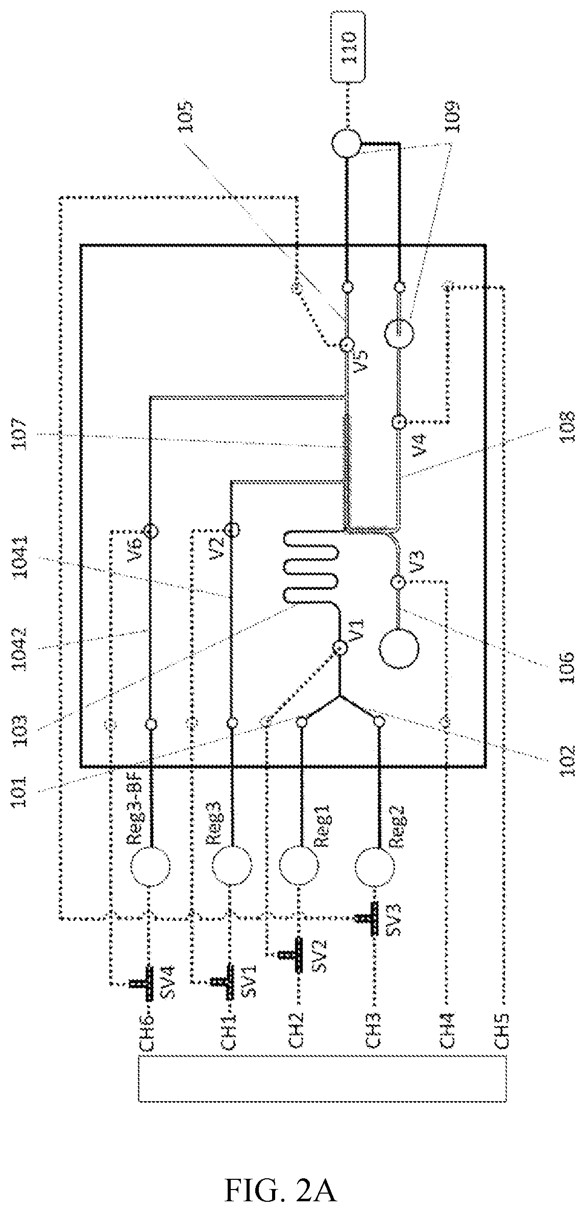
[0052]The microfluidic chip of the examples is used for treating human oocytes, bovine oocytes, or bovine embryos with a cell size of 120-150 microns, wherein the inner diameter of each channel is about 200 micrometers. The inner diameter of the end of the cell retrieving channel 108 gradually changes from 200 micrometers to 300 micrometers and then changes to the cell retrieving hole with an inner diameter of about 650 micrometers. The micropillar is a cuboid with a length, width, and height of 100 micrometers by 100 micrometers by 200 micrometers, and the gap between the micropillars is set at about 50 micrometers.
[0053]Example 1 A bovine embryo was treated with the microfluidic chip, as shown in FIG. 2A. The detailed operation process was as follows:
Step 1: Washing the Chip with a First Reagent Reg1
[0054]The first reagent Reg1 was placed into the liquid reservoir (Reg3) at the inlet of the third reagent...
example 2
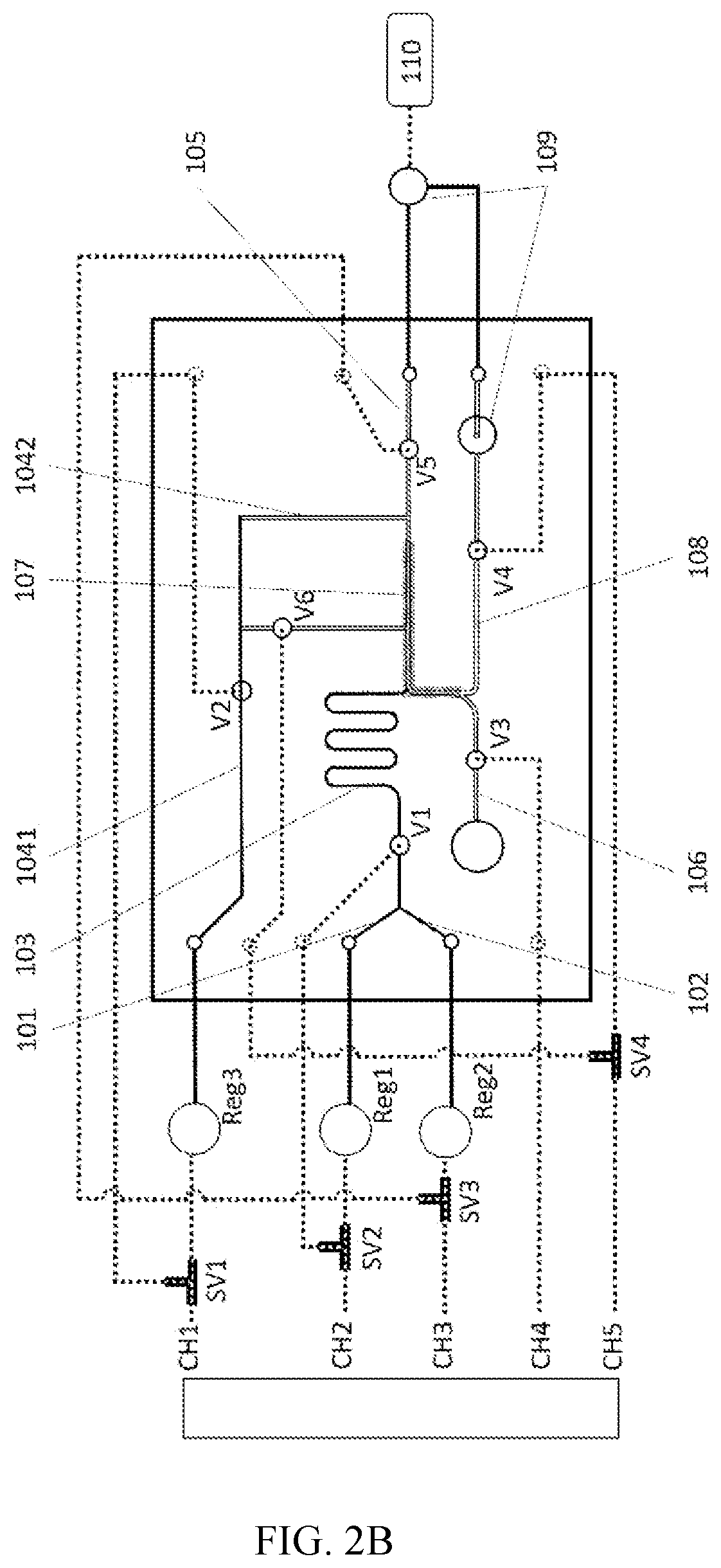
[0064]A human oocyte was treated with the microfluidic chip, as shown in FIG. 2B. The detailed operation process was as follows:
Step 1: Washing the Chip with a First Reagent Reg1
[0065]The first reagent Reg1 was placed into the liquid reservoir at the inlet of the third reagent inflow channel 1041. Then, the gas pressure-supplying direction of the gas switching valves SV1, SV2, and SV3 was adjusted to the direction of the fluidic (as shown by the black line in FIG. 2), while the negative pressure device was kept closed.
[0066]The pneumatic channel CH2 was pressurized and the switching valve SV2 was switched to V1 position, and the built-in pneumatic micro-valve V1 was closed; the pneumatic channel CH4 was pressurized and the built-in pneumatic micro-valve V3 was closed; the pneumatic channel CH1 was pressurized, and Reg1 was driven to wash the internal fluidic pipeline of the chip and was finally discharged into the waste liquid reservoir 109 outside the chip through the negative pres...
PUM
 Abstract
Description
Claims
Application Information
 - R&D
- Intellectual Property
- Life Sciences
- Materials
- Tech Scout
- Unparalleled Data Quality
- Higher Quality Content
- 60% Fewer Hallucinations
Browse by: Latest US Patents, China's latest patents, Technical Efficacy Thesaurus, Application Domain, Technology Topic, Popular Technical Reports.
© 2025 PatSnap. All rights reserved.Legal|Privacy policy|Modern Slavery Act Transparency Statement|Sitemap|About US| Contact US: help@patsnap.com


