Computer implemented process to enhance edge defect detection and other defects in ophthalmic lenses

a technology of edge defect detection and ophthalmic lens, which is applied in image enhancement, instruments, biological models, etc., can solve the problems of reducing productivity, reducing the efficiency of critical defect data, and high resolution cameras that only add to the productivity decline, so as to reduce or re-arrange the image, eliminate redundant pixels surrounding the edge, and facilitate processing

Pending Publication Date: 2021-08-26
EMAGE AI PTE LTD
View PDF2 Cites 1 Cited by
  • Summary
  • Abstract
  • Description
  • Claims
  • Application Information

AI Technical Summary

Benefits of technology

[0006]One of the advantages of reducing or rearranging the image is to eliminate redundant pixels surrounding the edge of the lens. Subsequently by simultaneously dividing the image to a predetermined size of images that are easily processed by the deep learning modules for enhanced defect detection, in terms of speed and accuracy.
[0007]One of the objectives of this invention is to provide a high resolution and optimised preprocessed image of a contact lens' circular edge without compressing or distorting the pixel data.
[0008]Another aspect of the invention is to reconstruct and rearrange the circular edge of the Contact lens in a way to aid in faster processing of the image. This is accomplished by detecting the edge of the circular contact lens, unwrapping the edge and transforming it to a Horizontal edge. The image is further optimized by deleting redundant pixel data around the edge to minimise the size of the image.
[0009]One of the advantages of arranging the pixels as horizontal and vertical edges improve the processing and this helps the algorithm to process the images faster. In other words the processing speed is substantially improved. The algorithm may be an edge detection algorithm.
[0010]Another advantage of stacking the predetermined size of images (image area segments) vertically so as to form a square image, is that the length and breadth of the square image are the same. For e.g. when scanning a square image, pixel by pixel would require less computation than scanning a rectangular image. The advantage is speed of computations, not less number of computations. For example, it is significantly faster to process a square image compared to a rectangular image.
[0011]Another objective of the invention is to further rearrange the Horizontal edge that are divided into smaller lengths that overlap each other, and stacking them one above the other to generate a square image with all edge data, that suits the requirement of any neural network's input layer, and avoid padding the image with redundant black pixel data to achieve a square size.

Problems solved by technology

Every additional algorithm adds to the inspection time resulting in lower productivity.
. . etc have helped improve image processing speeds, but the ever increasing size of images acquired from High resolution cameras has only added to decreased productivity.
However, as image sizes have increased significantly, image compression algorithms are introduced to minimise the pixel data leading to degradation of critical defect data.
The quality of inspection is therefore affected and the efficiency of the next process suffers.
An increase in image size negatively impacts the performance of neural networks and deep learning methods.
The current technology lacks in using software methods without compromising the inspection quality especially when micro defect identification and feature extraction is a fundamental requirement for an inspection system when processing high resolution images.

Method used


Image

  • Computer implemented process to enhance edge defect detection and other defects in ophthalmic lenses
  • Computer implemented process to enhance edge defect detection and other defects in ophthalmic lenses
  • Computer implemented process to enhance edge defect detection and other defects in ophthalmic lenses

Examples


Embodiment Construction

[0024]In the following description of the preferred embodiments of the present invention, reference is made to the accompanying drawings that form a part hereof, and in which is shown by way of illustration specific embodiments in which the invention may be practiced. It is understood that other embodiments may be utilized and structural changes may be made without departing from the scope of the present invention.

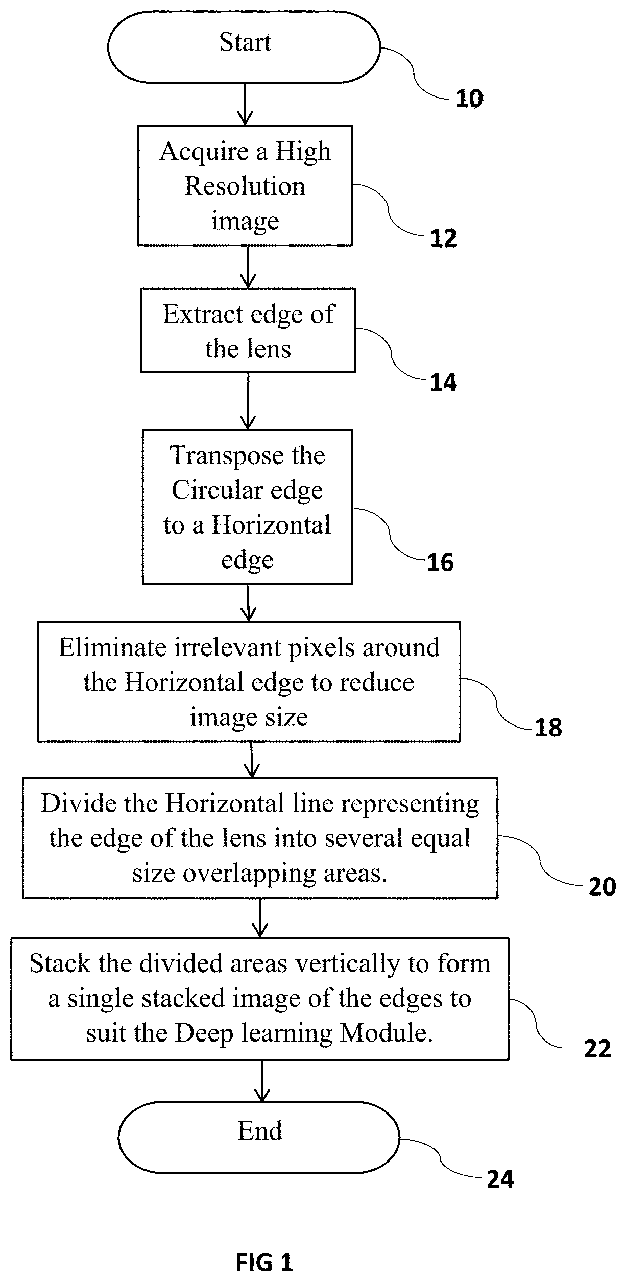
[0025]A general flow chart of the system and method according to the invention is shown in FIG. 1. The system 10 begins by acquiring a high resolution image of a contact lens in acquiring process action 12. The acquired image is then processed to extract the lens circular edge in extraction process action 14. The extracted circular edge is then transposed to a Horizontal image in transposition process action 16. In elimination process action 18, irrelevant pixel data around the horizontal edge is eliminated to minimize the size of the image. The horizontal edge image is su...


PUM


Abstract

The invention is a computer implemented process directed towards a Deep learning neural network architecture to create object detection model using high resolution images. More specifically, the invention is directed towards enhancing the classification accuracy and reliability of edge inspection in contact lenses. The invention is a Computer implemented process to represent a software architecture comprising software components and their inter dependencies that represents the core functional modules of an application. The system and method of the invention captures a high resolution image, transforms the circular edge of the lens to a Horizontal line representing the circular edge, restricting the image size by eliminating the pixel information around the edge, dividing the horizontal edge image into overlapping portions, and stacking the extracted images vertically to form a single high-resolution image that is ideal to be processed and analysed by Convolution Neural networks after augmenting the original image dataset with new images generated by Generative Adversarial Networks, to enable accurate classification of the defects.

Description

FIELD OF THE INVENTION[0001]The invention is related to achieving and maintaining high resolution images of contact lenses by extracting specific relevant pixel data and removing irrelevant data thereby increasing the efficiency of the image classification process in terms of accuracy and speed. The increase in efficiency is achieved through re-arranged and re-constructed images which aids in speedy training of inspection systems using neural networks and applying the trained decision making models during inspection of contact lenses in automated systems.BACKGROUND OF THE INVENTION[0002]Contact lens defect inspection systems and methods continue to evolve towards increased efficiency while lowering costs. Pattern recognition, image correlation, Histogram equalization, Dithering . . . etc are some of the common image processing algorithms that are commonly used in inspection methods. As the defect inspection criteria becomes more stringent, additional algorithms are implemented to im...

Claims


Application Information

Patent Timeline
Patent Type & Authority Applications(United States)
IPC IPC(8): G06T7/00G06N3/08G06N3/04G06T5/00G06T7/11G06T7/13G06V10/25G06V10/26G06V10/32G06V10/34G06V10/764
CPCG06T7/0004G06N3/08G06N3/0454G06N3/0427G06T5/002G06T2207/20084G06T7/13G06T2207/30108G06T2207/20021G06T2207/20081G06T7/11G01N21/958G06T7/10G01N2021/9583G06T2207/10004G06T2207/20192G06V20/52G06V10/94G06V10/26G06V10/32G06V10/34G06V10/454G06V10/25G06V2201/06G06V20/66G06V10/82G06V10/764G06N3/047G06N3/045G06T1/20G06F18/24G06N3/042
Inventor WONG, SOON WEISRINIVAS, KUNDAPURA PARAMESHWARA
Owner EMAGE AI PTE LTD
Why Eureka
Try Eureka