High-Efficiency End-Fire 3D Optical Phased Array Based On Multi-Layer Platform

Pending Publication Date: 2021-09-02
THE RGT OF THE UNIV OF MICHIGAN
View PDF0 Cites 0 Cited by
  • Summary
  • Abstract
  • Description
  • Claims
  • Application Information

AI Technical Summary

Benefits of technology

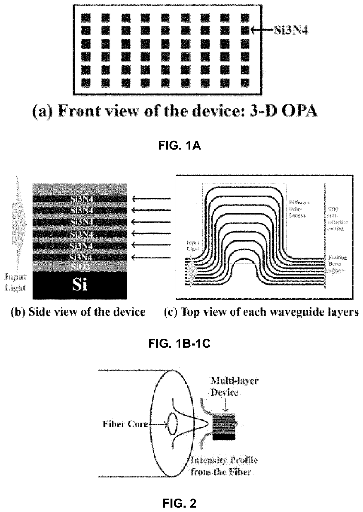
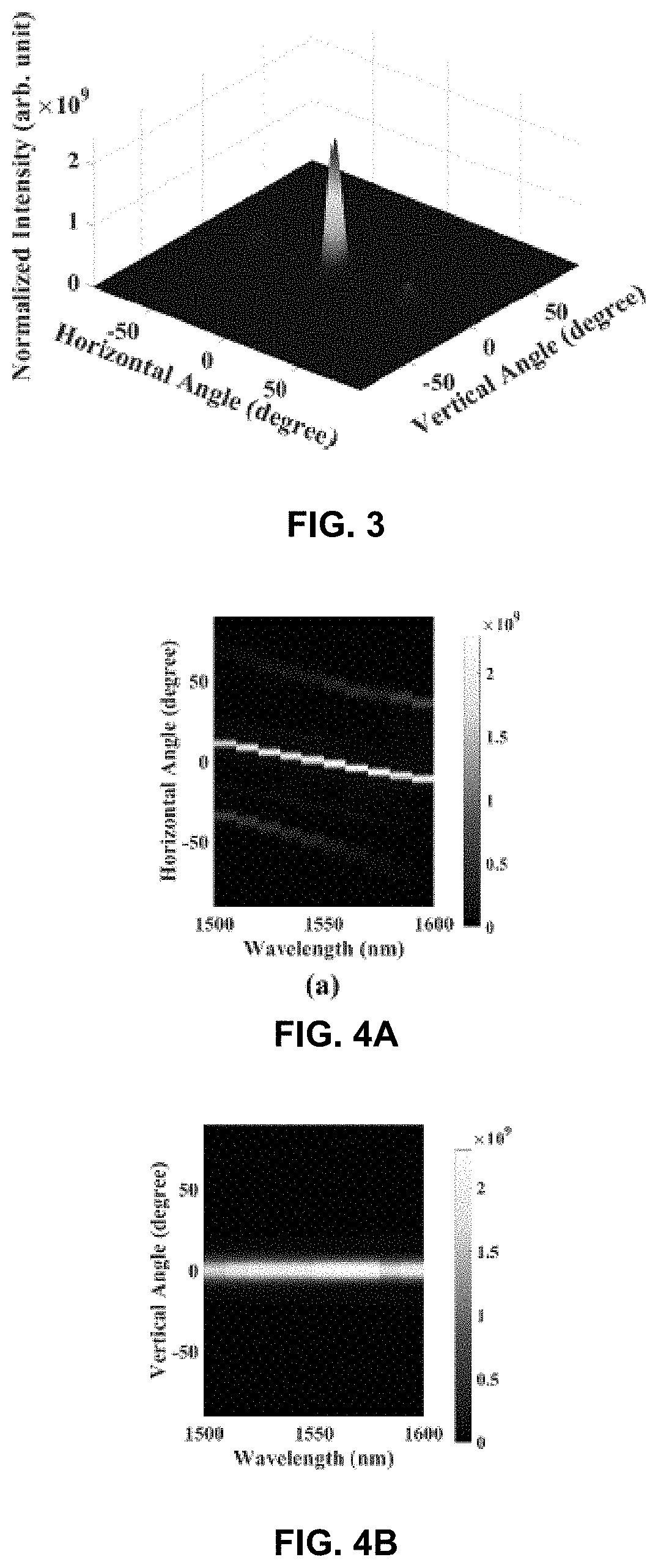
This patent describes a method for making a device called a 2-D optical phased array (2-D OPA) using a multi-layer structure on a silicon substrate. The device is designed to generate a 2-D converged beam with high efficiency. The method involves first creating a SiO2 layer and then patterning multiple layers of Si3N4, a material that has low etching selectivity. A combination of the self-aligning method and a multi-layer etching process can be used to achieve precise thickness control. The 2-D OPA is formed on the side wall of the device, facing the air, and its backward emitting is suppressed, resulting in an emitting efficiency of ˜70% in the whole wavelength range from 1500 nm to 1600 nm. This efficiency is significantly higher than a single layer 2-D OPA, which emits beam upwards.

Problems solved by technology

This typically results in relatively low emitting efficiency.

Method used


Image

  • High-Efficiency End-Fire 3D Optical Phased Array Based On Multi-Layer Platform
  • High-Efficiency End-Fire 3D Optical Phased Array Based On Multi-Layer Platform
  • High-Efficiency End-Fire 3D Optical Phased Array Based On Multi-Layer Platform

Examples


Embodiment Construction

[0053]Example embodiments will now be described more fully with reference to the accompanying drawings.

[0054]Example embodiments are provided so that this disclosure will be thorough, and will fully convey the scope to those who are skilled in the art. Numerous specific details are set forth such as examples of specific components, devices, and methods, to provide a thorough understanding of embodiments of the present disclosure. It will be apparent to those skilled in the art that specific details need not be employed, that example embodiments may be embodied in many different forms and that neither should be construed to limit the scope of the disclosure. In some example embodiments, well-known processes, well-known device structures, and well-known technologies are not described in detail.

[0055]The terminology used herein is for the purpose of describing particular example embodiments only and is not intended to be limiting. As used herein, the singular forms “a,”“an,” and “the” ...


PUM


Abstract

Beam steering device such as optical phased array (OPA) is a key component in applications of solid-state LIDAR and wireless communication. The traditional single-layer OPA results in a significant energy loss due to the substrate leakage caused by the downward coupling from the grating coupler structure. In the present disclosure, we have investigated a structure based on multi-layers Si3N4 / SiO2 platform that can form a 3D OPA to emit the light from the edge of the device with a high efficiency, a 2D converged out-coupling beam will be end-fired to the air. The high efficiency and wide horizontal beam steering are demonstrated numerically, the influence of vertical crosstalk, the delay length, number of waveguide layers, and the fabrication feasibility are also discussed.

Description

CROSS-REFERENCE TO RELATED APPLICATIONS[0001]This application claims the benefit of U.S. Provisional Application No. 62 / 984,004, filed on Mar. 2, 2020. The entire disclosure of the above application is incorporated herein by reference.GOVERNMENT SUPPORT[0002]This invention was made with government support under ECCS1644731 awarded by the National Science Foundation. The government has certain rights in this invention.FIELD[0003]The present disclosure relates to a high-efficiency end-fire 3D optical phased array based on multi-layer platform.BACKGROUND AND SUMMARY[0004]This section provides background information related to the present disclosure which is not necessarily prior art. This section provides a general summary of the disclosure, and is not a comprehensive disclosure of its full scope or all of its features.[0005]With the emerging applications, such as solid-state LIDAR (light detection and ranging), beam steering based on integrated optical phased array (OPA) has drawn man...

Claims


Application Information

Patent Timeline
IPC IPC(8): G02F1/29G01S7/481
CPCG02F1/292G01S7/4814G02F2201/20G02F2203/24G01S7/4818G01S7/4817G02F1/2955G02F1/291
Inventor YI, YA SHAWU, DA CHUAN
Owner THE RGT OF THE UNIV OF MICHIGAN
Why Eureka
Try Eureka