Package structure of full color LED form by overlap cascaded die bonding
- Summary
- Abstract
- Description
- Claims
- Application Information
AI Technical Summary
Benefits of technology
Problems solved by technology
Method used
Image
Examples
first embodiment
[0035] Hereunder, an overlap cascaded three primary color dice packaging structure of a full color LED according to the present invention is described with reference to the attached drawings.
[0036] The LED dice used in this invention can be made with different type of material. The dice can be made by a conventional method accordance to the specification of this invention such as chip size, bias voltage, intensity, color and metal contact, etc.. The dice should be tested and classified before packaging.
[0037] In the following embodiments, a pc-board with reflective metal pattern on the pc-board for die bonding, after the first chip is bond on the pc-board, a second chip is overlap and cascaded bond on the first chip. Bonding can be thermal, ultrasonic or transparent epoxy adhesion. A third chip is also over lap and cascaded bond on the second chip. Wire bond is then connected the positive electrode to the source and the negative electrode to the ground.
[0038] FIG. 7 shows the top vi...
second embodiment
[0039] an full color LED packaging structure according to the present invention is made by overlap cascaded bonding of a yellow and a blue light LEDs in parallel with another overlap cascaded red and green light LEDs. This structure is suitable for far field observation and is described in FIG. 12 and FIG. 13. FIG. 12 is the plane view. FIG. 13 is the cross section along A-A line in FIG. 12. In order to simplify die bond and save energy, we do not use three primary color LEDs, instead we use only two LEDs in overlap cascaded, then package in parallel side-by-side with another two LEDs in overlap cascaded. This structure satisfy far field observation. Refer to FIG. 13, a reflective metal layer 801 (aluminum, copper or gold) with thickness of 1000 .ANG. to 20000 .ANG., the better of 2000 .ANG. to 5000 .ANG. is sputtered, evaporated or plated on a pc-board 405. Then prepare a first red LED chip 401, made by epitaxy a p-type InGaAlP on an n-type GaAs substrate with a traditional technol...
third embodiment
[0041] an overlap cascaded packaging structure full color LED according to the present invention is by using of the left part (the yellow and blue light LED chips in overlap cascaded package) or the right part (the red and green LED chips in overlap cascaded package) independently. By adjusting the bias of each LED and with a constant current to obtain a white light LED luminescence or a full color LED.
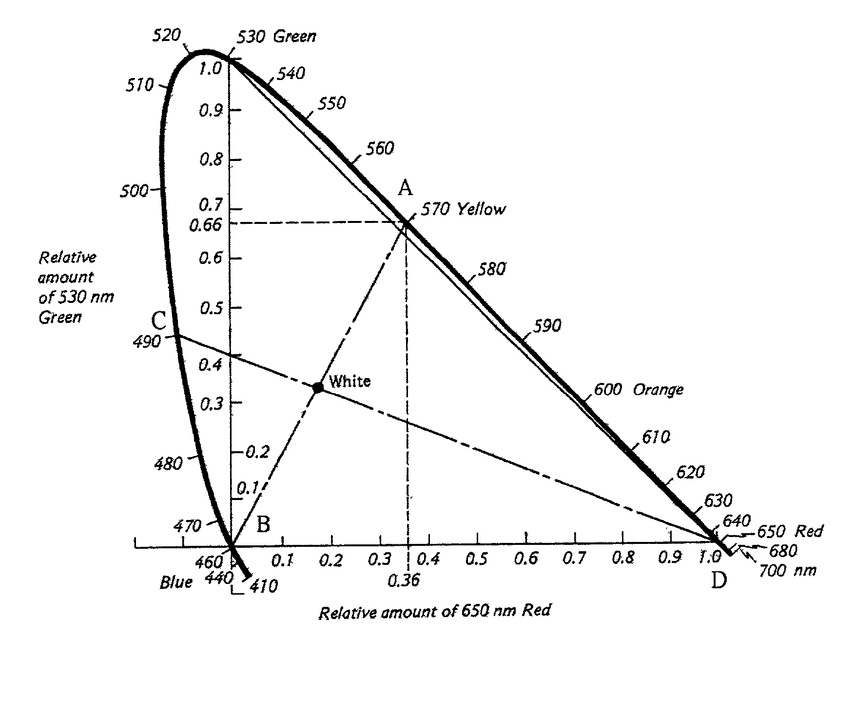
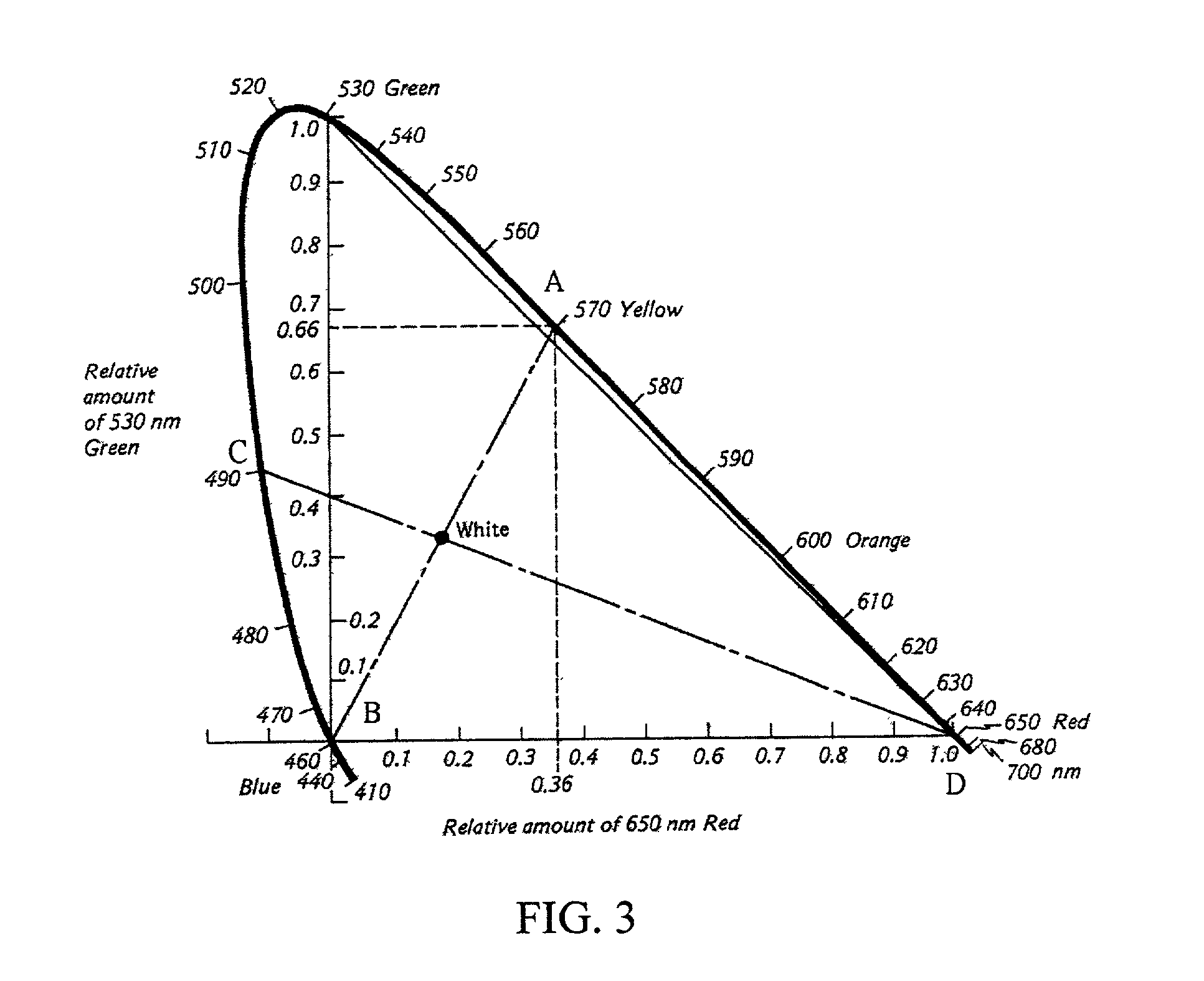
[0042] The third embodiment does not limit to overlap cascaded package of the yellow and blue LED chips or the red and green LED chips, any two complementary color with which obtain a white light after mixed can be used. The materials used to fabricate the red, green, blue and yellow LEDs are not limited to the above materials, the structure of the diode is not limited to pn-junction structure, those advance technology such as quantum well structure can be used.
PUM
 Abstract
Description
Claims
Application Information
 - R&D
- Intellectual Property
- Life Sciences
- Materials
- Tech Scout
- Unparalleled Data Quality
- Higher Quality Content
- 60% Fewer Hallucinations
Browse by: Latest US Patents, China's latest patents, Technical Efficacy Thesaurus, Application Domain, Technology Topic, Popular Technical Reports.
© 2025 PatSnap. All rights reserved.Legal|Privacy policy|Modern Slavery Act Transparency Statement|Sitemap|About US| Contact US: help@patsnap.com


