Filter, gas adsorption device using filter, and vacuum heat insulator
a technology of gas adsorption and filter, which is applied in the direction of pipe protection by thermal insulation, inorganic chemistry, domestic walls, etc., can solve the problems of deteriorating insulation performance, accelerating the deterioration of insulation performance, and deteriorating gas adsorption performance, etc., and achieves low melting point and easy control of breathability. , the effect of the size of the void
- Summary
- Abstract
- Description
- Claims
- Application Information
AI Technical Summary
Benefits of technology
Problems solved by technology
Method used
Image
Examples
first exemplary embodiment
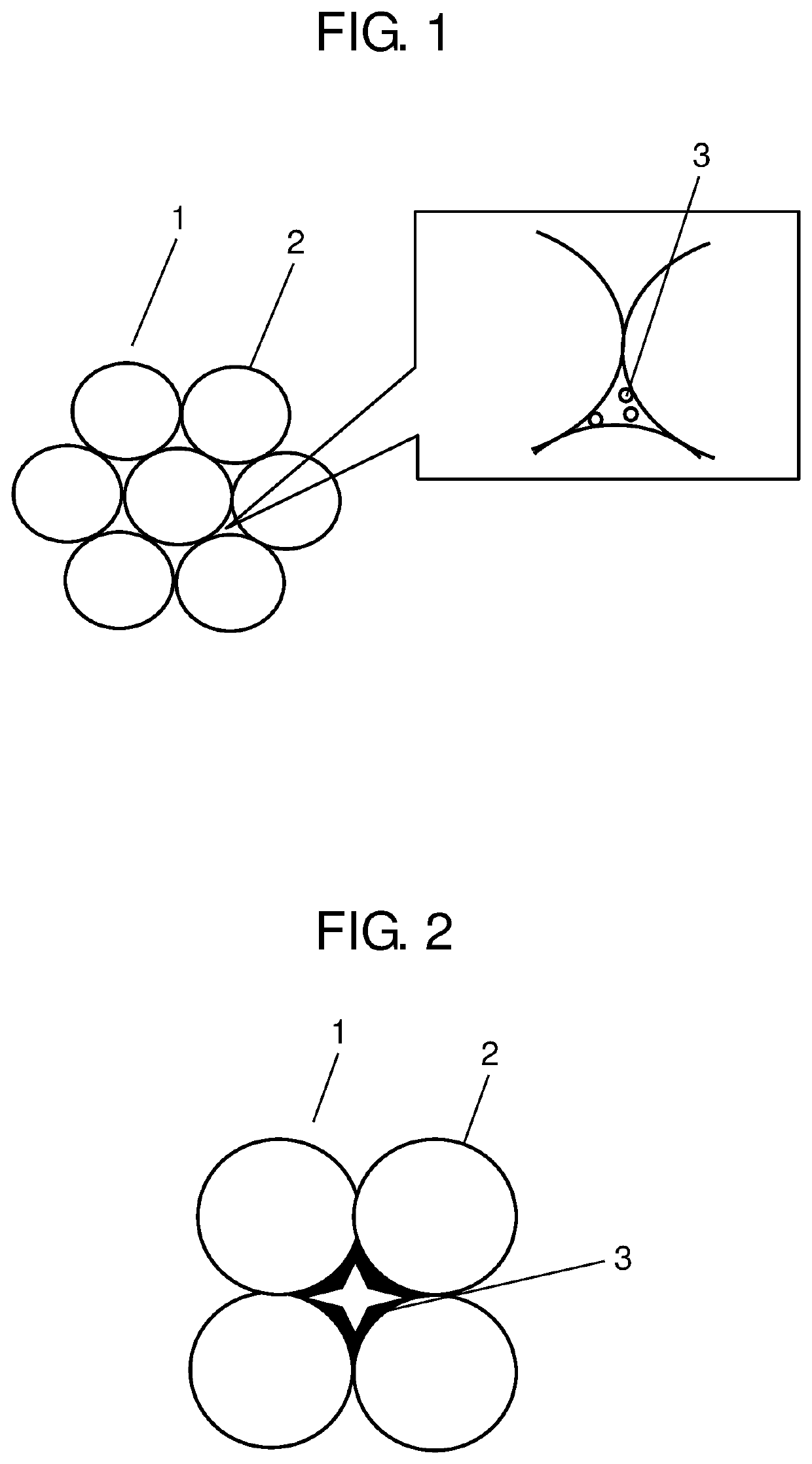
[0053]FIG. 1 is a schematic diagram of a filter according to a first exemplary embodiment of the present disclosure.
[0054]In FIG. 1, filter 1 is a porous body having voids contiguous at least in the direction perpendicular to the plane of FIG. 1. Filter 1 has a primary structure composed of material 2 (also referred to as the first material) with a relatively high melting point. Filter 1 further has material 3 (also referred to as the second material) with a relatively low melting point, which is held in voids around the primary structure.
[0055]The filter of the present disclosure can be fabricated as follows.
[0056]First, material 2 with the relatively high melting point, for example, alumina powder, is molded by a well-known method. To be more specific, the alumina powder is injected into a cylindrical mold and uniaxially molded. The molded product is heat-treated. These steps produce the primary structure, which is composed of material 2 with the relatively high melting point and ...
second exemplary embodiment
[0068]FIG. 2 is a schematic diagram of filter 1 according to a second exemplary embodiment of the present disclosure.
[0069]In FIG. 2, filter 1 is a porous body having voids contiguous at least in the direction perpendicular to the plane of FIG. 2. Material 2 with a relatively high melting point composes a primary structure. Material 3 with a relatively low melting point is held in voids around the primary structure.
[0070]Filter 1 of the present exemplary embodiment can be obtained as follows.
[0071]First, material 2 (e.g., alumina powder) is mixed with material 3 (e.g., borosilicate glass powder) by a well-known method. The resultant mixture is molded by a well-known method. To be more specific, the mixture is injected into a cylindrical mold and uniaxially molded. The molded product is heat-treated to obtain filter 1 including material 2, which composes a primary structure, and material 3, which is held in voids around the primary structure.
[0072]Material 2 and material 3 both in po...
third exemplary embodiment
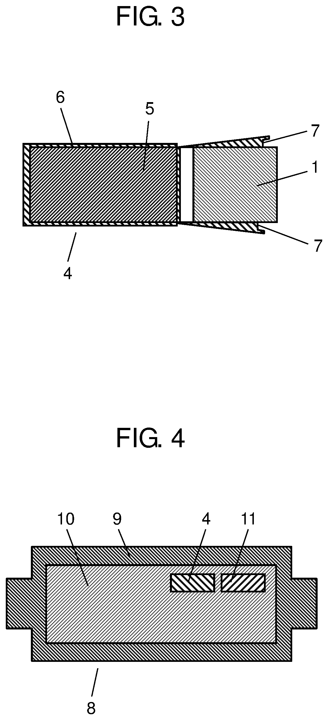
[0078]FIG. 3 is a cross-sectional schematic diagram of gas-adsorption device 4, which includes filter 1, according to a third exemplary embodiment of the present disclosure.
[0079]In FIG. 3, gas-adsorption device 4 includes filter 1; gas adsorber 5 composed of copper ion-exchanged ZSM-5 zeolite; low-gas-permeable container 6; and sealing glass 7. Filter 1 is the same as that used in the first or second exemplary embodiment.
[0080]Gas-adsorption device 4 of the present disclosure can be obtained as follows.
[0081]First, low-gas-permeable container 6 gets filled with copper ion-exchanged ZSM-5 zeolite, which is gas adsorber 5.
[0082]Next, filter 1 gets located in low-gas-permeable container 6 with its flared opening at the top as shown in FIG. 3.
[0083]The opening of container 6 is larger in diameter than filter 1 at the end position, becomes smaller with distance from the end position, and is smaller than filter 1 in the region opposite to the end position. Therefore, filter 1 moves downw...
PUM
| Property | Measurement | Unit |
|---|---|---|
| melting point | aaaaa | aaaaa |
| diameter | aaaaa | aaaaa |
| particle size | aaaaa | aaaaa |
Abstract
Description
Claims
Application Information
 - R&D
- Intellectual Property
- Life Sciences
- Materials
- Tech Scout
- Unparalleled Data Quality
- Higher Quality Content
- 60% Fewer Hallucinations
Browse by: Latest US Patents, China's latest patents, Technical Efficacy Thesaurus, Application Domain, Technology Topic, Popular Technical Reports.
© 2025 PatSnap. All rights reserved.Legal|Privacy policy|Modern Slavery Act Transparency Statement|Sitemap|About US| Contact US: help@patsnap.com


