
Device for Monitoring a Set of Bearings

Pending Publication Date: 2021-09-30
METHODE ELECTRONICS MALTA
View PDF14 Cites 0 Cited by
  • Summary
  • Abstract
  • Description
  • Claims
  • Application Information

AI Technical Summary

Benefits of technology

The patent describes a device for monitoring the operating temperature of bearings in a vehicle. The device is powered by electrical energy and includes a temperature sensor and a controller. The controller identifies the individual set of bearings that exceed a threshold temperature and sends signals to the temperature sensor. The device can be located radially between a shaft and a hub of a wheel or in any other component of the vehicle. The device helps to prevent damage to the bearings and ensures efficient operation of the vehicle.

Problems solved by technology

A catastrophic failure of a set of bearings can lead to the wheel of the vehicle catch fire, which again may eventually lead to a burning truck on the side of the road.
A leakage of oil and a sudden failure of the functioning of the set of bearings in the hub of a wheel may be the consequence.
Should the lubricant and / or a lubricating film inside the set of bearings be defective, degraded or leaked, increased friction coefficient will result in rapid wear and the operating temperature of the set of bearings rises.
A further rise of the operating temperature causes more friction and wear until the bearing destroys itself.
This may set the wheel of the vehicle associated to the set of bearings on fire and / or may cause loss of control of the vehicle and / or trailer.
At best case, sudden bearing failure will cause extensive down time for the truck.
The specific location of the device for monitoring a set of bearings on the hub of a wheel (carrier) and the susceptibility of the device for monitoring the set of bearings to a large environment and / or to mechanical vibrations can lead to defective hard wired connections between the device for monitoring the temperature of a set of bearings and the receiver at the user end, typically driver console in the cabin.
When driving, there is the risk that at least one of the hubs (carrier) and / or the corresponding wheel of the truck is damaged due to an overheated sets of bearings.
As a consequence, the lubricant inside of the set of bearings loses its lubricating ability.
This results in the temperature and friction to increase without control resulting in the eventual wear and destruction of the bearing with resulting down-time, potential fire and loss of control of the vehicle.
Once said threshold temperature of 120° C. is exceeded by the operating temperature of the hub of a wheel a failure of lubrication within the bearings leads to a rapid and sudden failure of set bearings on the individual hub of a wheel.

Method used


Image

  • Device for Monitoring a Set of Bearings
  • Device for Monitoring a Set of Bearings
  • Device for Monitoring a Set of Bearings

Examples


Embodiment Construction

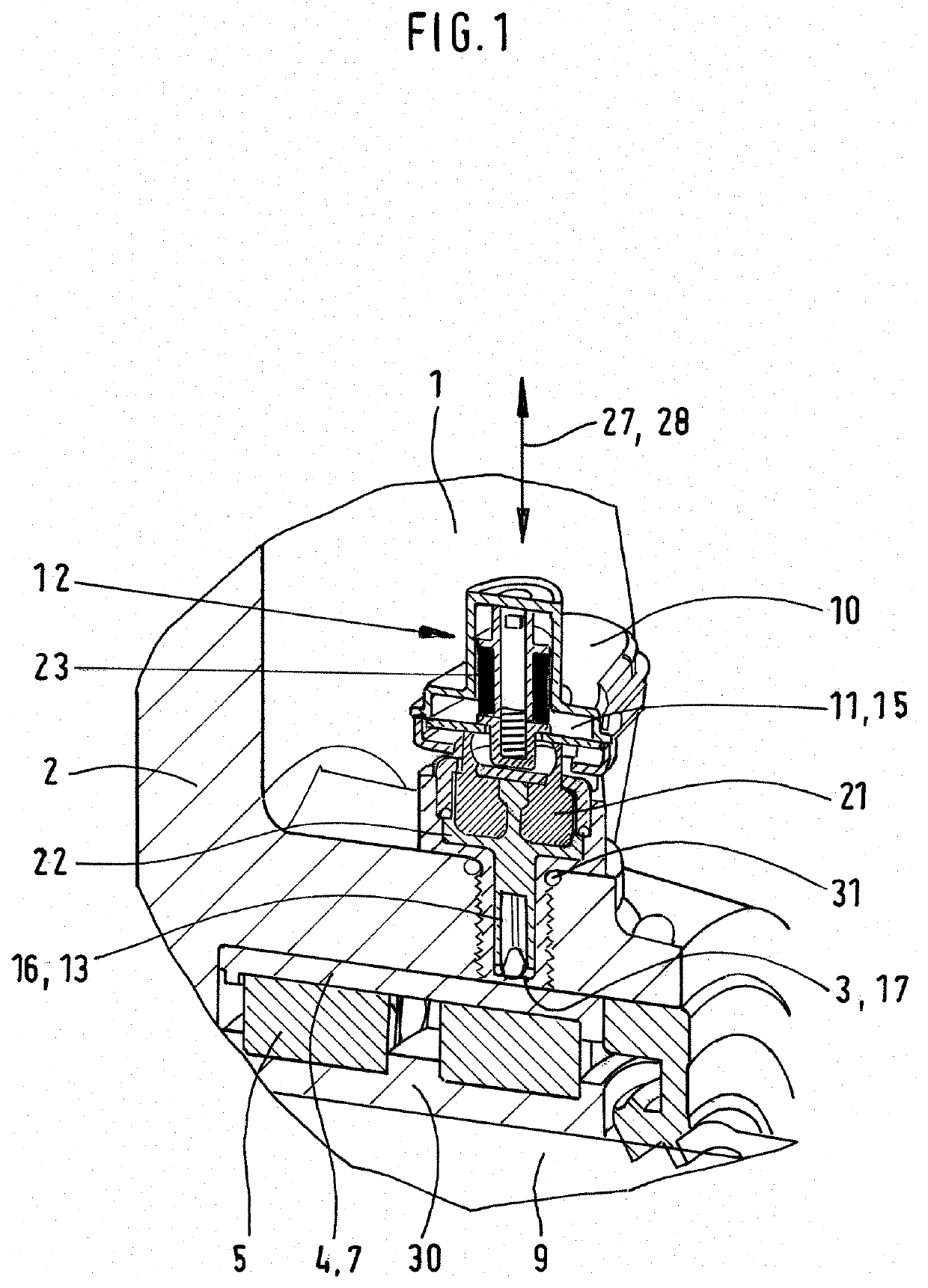
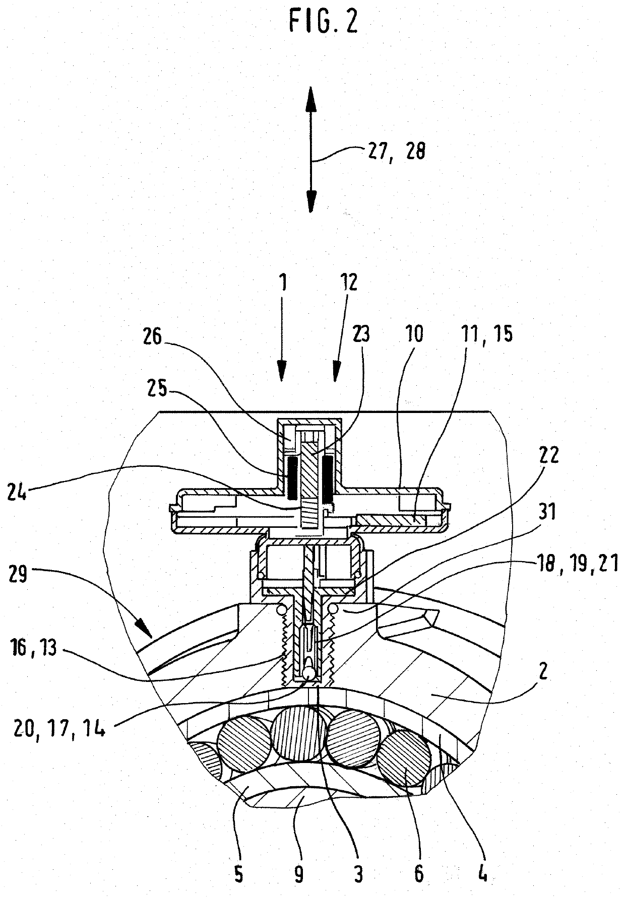
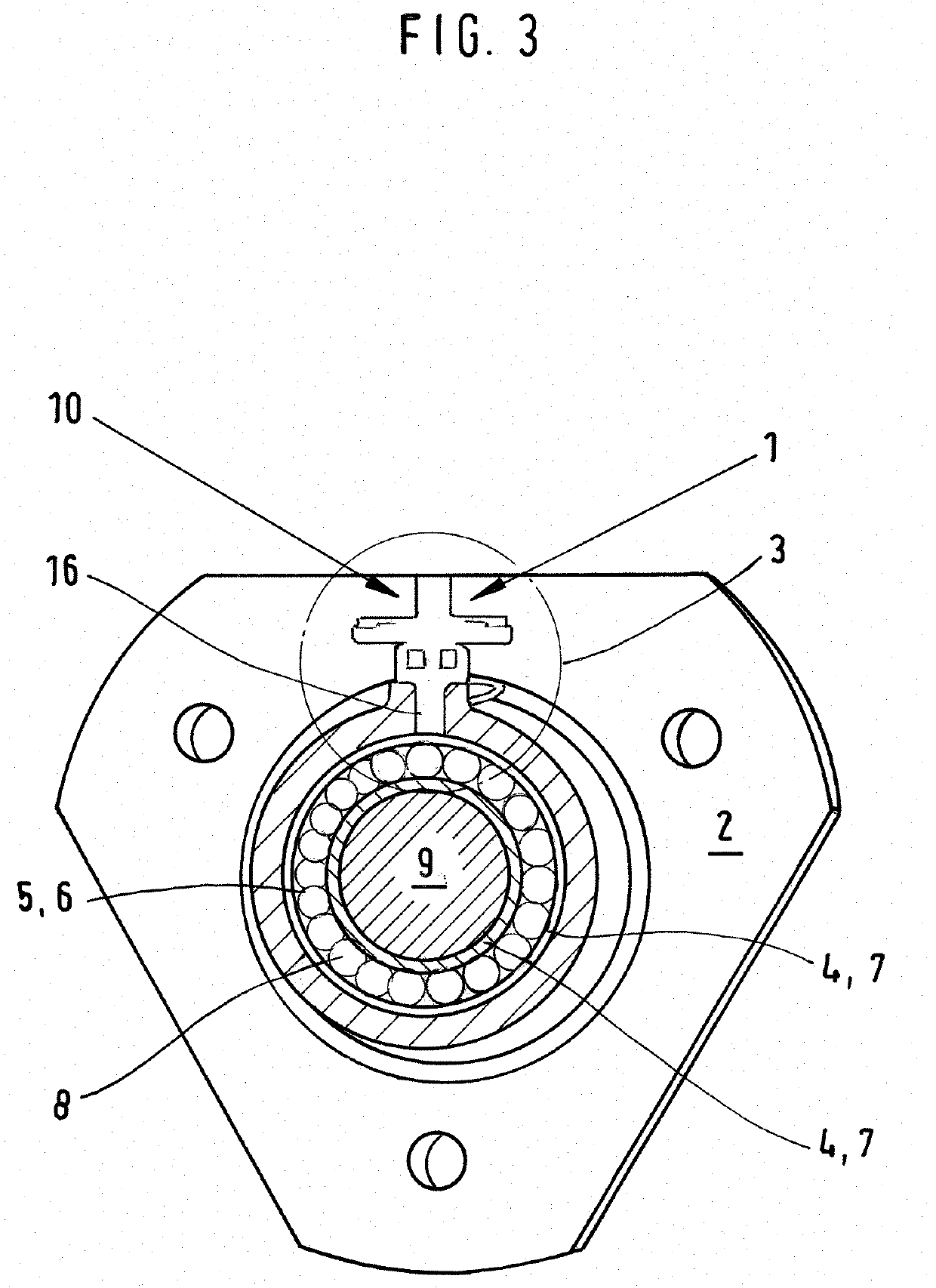
[0179]The FIGS. 1 to 3 show a device for monitoring a set of bearings 1 which is mounted onto a hub of a wheel 2 (carrier).

[0180]The device for monitoring the set of bearings comprises a temperature sensor 3 which is positioned neighboring and / or adjacent to set of bearings 5. The set of bearings 5 comprises a casing 4.

[0181]In the FIGS. 1 to 3, the set of bearings 5 is designed as a ball bearing, comprising two rolls of balls 6.

[0182]The balls 6 of the set of bearings 5 are arranged adjacent to each other within races 7 of the set of bearings 5.

[0183]A lubricating grease 8 is arranged inside of the set of bearings 5.

[0184]Said lubrication grease 8 avoids at least two separate mechanical components rubbing against each other. Lubricating grease 8 avoids friction between the balls 6 of the set of bearings 5 and the races 7. Said friction between the metal components of the set of bearings 5 leads to an augmentation of the operating temperature in the set of bearings.

[0185]A shaft or ...


PUM


Abstract

A device monitors the operating temperature of at least one set of bearings in a plurality of sets of bearings. The at least one set of bearings is arranged between a shaft and a carrier. The carrier has at least one temperature sensor that senses the temperature of the at least one set of bearings and generates a signal representative of an operating temperature of the at least one set of bearings. The at least one temperature sensor is operatively electrically connected to at least one controller. The controller processes the signal from the temperature sensor, including determining the operating temperature of the respective at least one set of bearings and whether the operating temperature of the respective at least one set of bearings exceeds at least one threshold temperature. The controller memory holds a unique identifier associated with the at least one bearing set.

Description

RELATED APPLICATION[0001]This application claims the benefit of German patent application ser. no. DE 10 2020 108 638.5 filed on Mar. 27, 2020, the disclosure of which is incorporated by reference herein.BACKGROUND AND SUMMARY[0002]The disclosure refers to a device for monitoring the operating temperature of at least one set of bearings of a multitude of sets of bearings.[0003]EP 1 356 530 B1 reveals an apparatus for suppling power to a sensor. Said apparatus has a piezo-electric transducer. The transducer can be deformed by a mechanical energy store. It supplies an electrical voltage for the operation of said sensor.[0004]Nowadays consumers are looking for sensors which are electrically powered. However, said sensor is expected be energy efficient and should not suffer from connector and / or cable failure issues. Also, the sensor should be able to send signals which differ from each other, depending on the magnitude of the parameter, the sensor is measuring.Solution[0005]By way of e...

Claims


Application Information

Patent Timeline
IPC IPC(8): F16C19/52F16C41/00
CPCF16C19/525F16C2233/00F16C41/004F16C2326/02F16C41/00F16C43/04G01K3/00G01K1/022G01K1/024G01M13/04G01K1/14G01K1/16G01K2215/00G01K1/08
Inventor GALEA, ALEXANDER
Owner METHODE ELECTRONICS MALTA
Learn More