Distributed Airborne Electromagnetic Detection System

a technology of electromagnetic detection and airborne, applied in the field of geophysical exploration, can solve the problems of difficult to achieve rapid large-scale coverage, low detection efficiency, and relatively high cost, and achieve the effect of reducing the distance between the uav and the transmitting loop structure, high economic efficiency, and high performan

Inactive Publication Date: 2021-09-30
WU XIN +2
View PDF0 Cites 5 Cited by
  • Summary
  • Abstract
  • Description
  • Claims
  • Application Information

AI Technical Summary

Benefits of technology

[0034]The distributed airborne electromagnetic detection system of the present disclosure does not require high performance or high economical efficiency for a single UAV because a plurality of UAVs are used to carry the basic constitutional units, namely the electromagnetic detection system such as the transmitter, the transmitting loop, the receiver and the sensor, respectively. Under precise synchronous flight conditions, the distance between a UAV and a transmitting loop structure can be greatly reduced, thereby significantly reducing the length of unwanted transmitting cable. In addition, due to the better low-altitude low-speed performance of UAVs, the traveling speed of the entire system can be further reduced, so that higher quality data can be obtained. Moreover, the present disclosure also has the advantage that the performance parameters (e.g., magnetic moment and observation) of the carried system can be regulated according to application scenarios and detection requirements, so as to further improve the technical solution of airborne electromagnetic detection.

Problems solved by technology

This method, however, may have low detection efficiency in areas such as Gobi, deserts, gullies or dense river networks, and forests, and thus be difficult to achieve rapid large-scale coverage.
However, the development of the ATEM technology based on fixed-wing aircraft requires modification of the aircraft and needs a professional team to maintain the system including the aircraft, which is relatively high in cost.
In developing countries including China, the density of a navigable airport is limited, and if a measurement area is far from the airport, the round-trip flight will actually limit the application efficiency.
However, existing HTEM systems have still been limited by the technical performance of the flying platform, and have limitations in the aspects of technologies and applications.
It is difficult for existing systems to carry out deep detection in plateau areas for the following reasons: at present, the respective major HTEM models of the international mainstream HTEM detection service providers basically have peak transmitting magnetic moments of above 0.6 MAm2.
When a plateau area at an altitude of more than 3500 m is to be detected, helicopters, often used as carrying platforms in plain areas, such as Eurocopter AS350B3 and mainstream general-purpose models of the same class from other companies, can hardly ensure sufficient lift for flight safety.
The difficulty of solution 1 is as follows: in many countries, there are few large-load helicopters that provide commercial operations; and even if such large-load helicopters are available, the flight services thereof may be expensive.
The difficulty of solution 2 is that installing a lighter system instead will directly result in substantial decrease in the system's transmitting magnetic moment, which makes it difficult to achieve the deep detection.
1) Because a common HTEM system needs to be powered by an aircraft, a transmitter is generally installed in a rear passenger cabin of the aircraft. The aircraft is far away from the transceiver structure, which means that a transmitting cable, after being led out of the transmitter, has to go through a long distance to reach the transceiver structure. On the one hand, this long distance causes unnecessary line loss of transmission current, and on the other hand, it increases useless system weight.
2) An existing HTEM system uses an umbrella-shaped cable system. Such a system can better ensure the attitude of the transceiver structure when the flight speed is stable. However, when a helicopter alters its flight state or is hit by lateral airstream turbulence, the attitude of the transceiver structure and the relative geometric relationship between the transmitting loop and the sensor are both easy to change significantly and difficult to control. In fact, although existing systems mostly have various attitude sensors installed on the transmitting loop carrying structures, only the attitudes of the transmitting loop carrying structures can be observed, while it is completely impossible to control the attitudes of magnetic field sensors that observe the earth's response.
3) For ATEM observation, a relatively low flight speed can help improve the detection quality of the system. During HTEM detection, in order to ensure the safety, a helicopter generally needs to maintain a flight speed of more than 90 km / h, namely 25 m / s. If the fundamental frequency of transmission is 25 Hz, the distance that the system goes forward in one cycle is 1 m. Because a TEM method usually requires superposition to increase the signal-to-noise ratio, for an acceptable “point”, the number of cycles allowed to take part in superposition may be reduced at a high flight speed of the system, affecting the horizontal resolution of the system.

Method used


Image

  • Distributed Airborne Electromagnetic Detection System
  • Distributed Airborne Electromagnetic Detection System
  • Distributed Airborne Electromagnetic Detection System

Examples


Embodiment Construction

[0046]In order to illustrate the objectives, technical solutions and advantages of the present disclosure more clearly, the embodiments of the present disclosure will be described below with reference to the accompanying drawings. It should be noted that, in the case of no conflict, the embodiments in the present disclosure and features in the embodiments can be arbitrarily combined with each other.

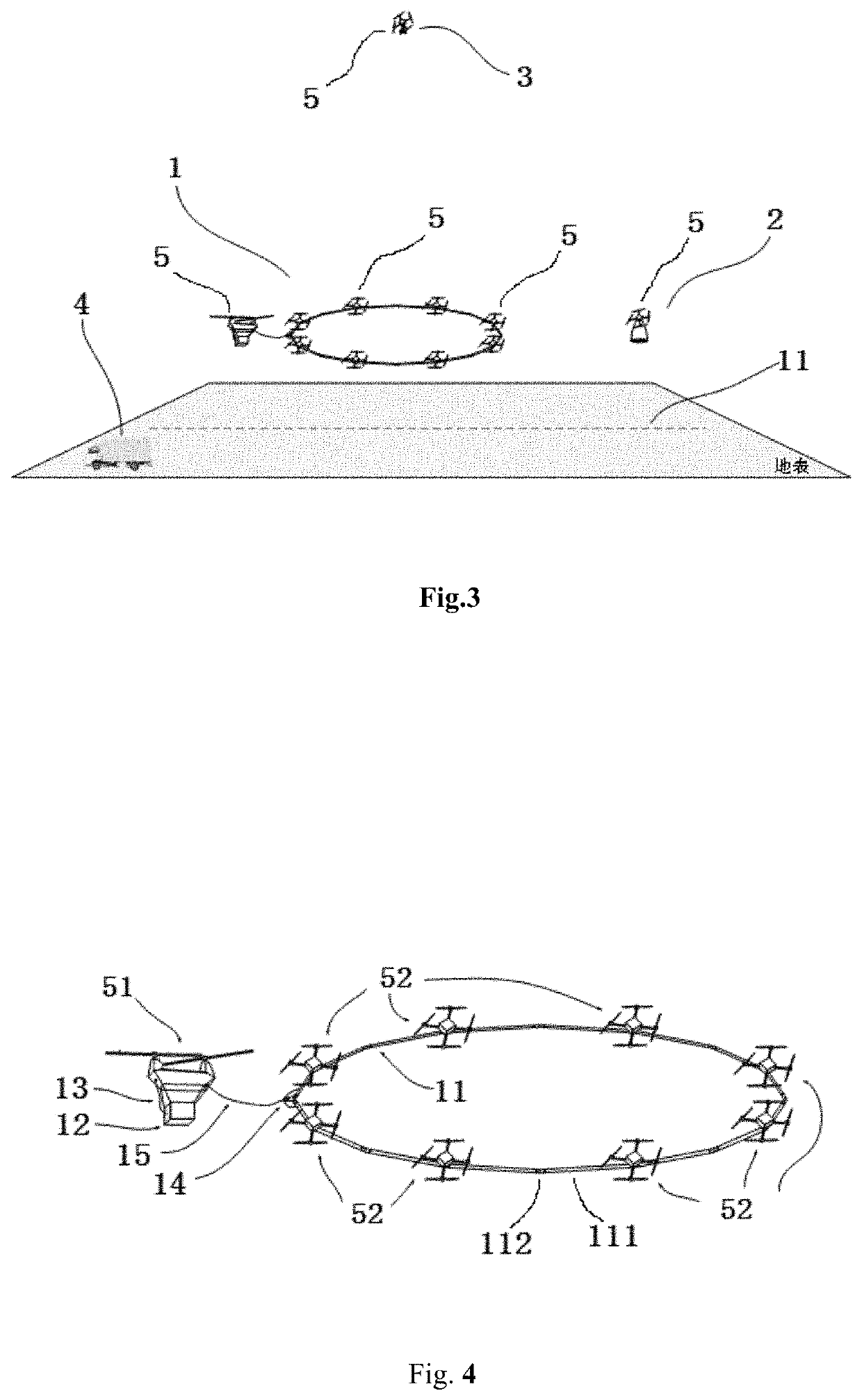
[0047]An embodiment of the present disclosure provides a distributed airborne electromagnetic detection system. FIG. 3 is a schematic structural diagram illustrating a distributed airborne electromagnetic detection system according to an embodiment of the present disclosure.

[0048]As shown in FIG. 3, the distributed airborne electromagnetic detection system comprises a transmitting system 1, a receiving system 2, a trunk module 3, an earth station 4, and several UAVs 5. The earth station 4 is arranged on the ground, and the transmitting system 1, the receiving system 2 and the trunk module...


PUM


Abstract

The present disclosure discloses a distributed airborne electromagnetic detection system, and relates to an airborne electromagnetic detection technology. The distributed airborne electromagnetic detection system comprises at least one transmitting system, at least one receiving system, at least one trunk module, and an earth station, and also a plurality of Unmanned Aerial Vehicles (UAVs) for carrying the transmitting system, the receiving system, and the trunk module. The distributed airborne electromagnetic detection system does not require high performance or high economical efficiency for a single UAV; under precise synchronous flight conditions, the distance between a type I UAV and a transmitting loop structure can be greatly reduced, thereby significantly reducing the length of unwanted transmitting cable; and in addition, due to the better low-altitude low-speed performance of UAVs, the traveling speed of the entire system can be further reduced, thus obtaining higher quality data.

Description

TECHNICAL FIELD[0001]The present disclosure relates to the field of geological exploration, and in particular to an airborne electromagnetic detection technology.BACKGROUND ART[0002]Electromagnetic methods, which are geophysical prospecting methods based on the electromagnetic induction principle, can use natural or artificial sources to excite the earth and realize the extraction of underground electrical structural information by observing the regularities of temporal and spatial distribution of the earth's response electromagnetic field. Thus, the electromagnetic methods have been widely used in the fields of exploration of resources such as minerals and groundwater, geological mapping, environmental engineering and the like.[0003]The electromagnetic methods are classified into two categories according to the nature of response, namely, a Frequency Domain Electromagnetic Method (FDEM) for studying the relationship between the earth's steady-state response and frequency, and a Tim...

Claims


Application Information

Patent Timeline
Patent Type & Authority Applications(United States)
IPC IPC(8): G01V3/12G01V3/40B64C39/02G01V3/36
CPCG01V3/12G01V3/40B64C2201/027G01V3/36B64C2201/128B64C39/024G01V3/16B64U10/13B64U2101/00B64U2101/60
Inventor WU, XINXUE, GUOQIANGDI, QINGYUN
Owner WU XIN
Why Eureka
Try Eureka