
System and Method for Detecting Ice Formation on a Body

a technology of ice formation and system, applied in the field of system and a method for monitoring the formation of ice, can solve the problems of affecting the stability of the body, and forming unwanted ice around certain solids or bodies, so as to increase the reaction speed, reduce the reaction speed, and increase the reaction time. the effect of the differen

Pending Publication Date: 2021-10-14
INST NACIONAL DE TECNICA AEROESPACIAL
View PDF9 Cites 4 Cited by
  • Summary
  • Abstract
  • Description
  • Claims
  • Application Information

AI Technical Summary

Benefits of technology

The patent describes a device that can detect temperature variations quickly. It uses two optic fibers to measure the optical signal generated by an electro-optic module. When the temperature of the detectors changes, they reflect part of the optical signal in different ways. By analyzing these reflected signals, the device can calculate the temperature at the position where the detectors are located. The device is designed with two sealed capillaries, one made of metal and one made of polymer, which affect the reaction speed of the detectors.

Problems solved by technology

The formation and accretion of unwanted ice around certain solids or bodies is a trouble in many sectors.
This is the case, for example, in the aeronautical sector where the formation of ice on surfaces such as the wings, fuselage or aircraft engines causes a loss of the aerodynamic performances or causes damage to mobile structures.
Under these conditions, the aircraft loses its lift and this may cause the pilot to lose control of the aircraft.
However, if the detection of ice formation is not fast and effective, the cited counter measures lose effectiveness.
Said problem is accentuated, at the height ranges where aircrafts typically fly and where the presence of supercooled water is frequent, that is, liquid water below its freezing temperature.
Other technical applications, such as wind turbines and transmission lines, also suffer the effects of ice formation and accretion.
In the case of transmission lines, in cold regions, the formation of ice on the cables of the electric transport lines drastically increases the weight that the electrical towers have to support.

Method used


Image

  • System and Method for Detecting Ice Formation on a Body
  • System and Method for Detecting Ice Formation on a Body
  • System and Method for Detecting Ice Formation on a Body

Examples


Embodiment Construction

[0077]In the following description, for purposes of explanation and not limitation, details are set forth in order to provide a thorough understanding of the present invention. However, it will be apparent to those skilled in the art that the present invention may be practiced in other embodiments that depart from these details and descriptions without departing from the spirit and scope of the invention. Certain embodiments will be described below with reference to the drawings wherein illustrative features are denoted by reference numerals.

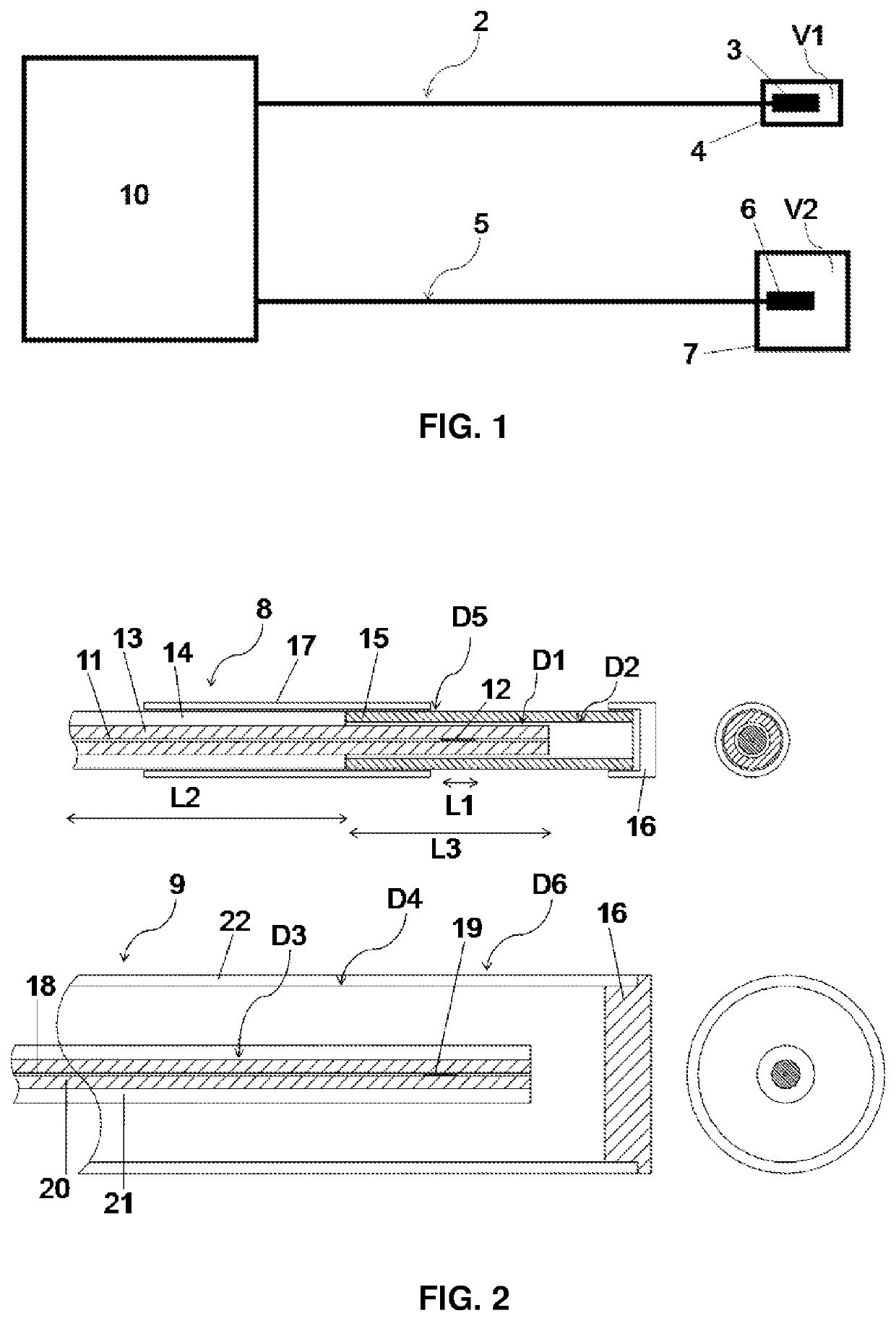
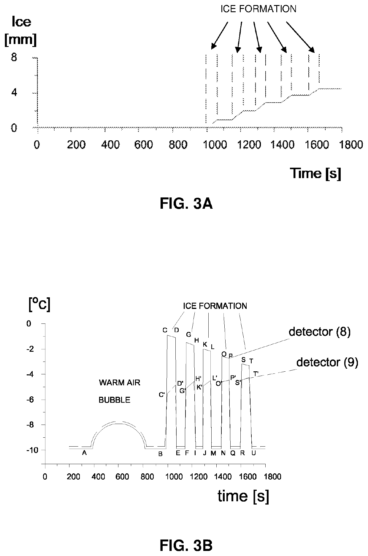
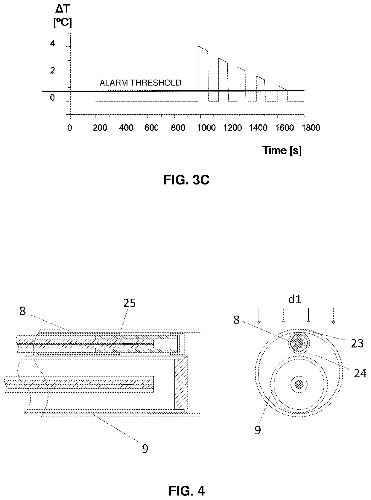
[0078]As described in previous sections and as represented in the figures, a main object of the invention is related to a system for detecting the ice formation and accretion on a body 1, preferably suitable for determining the almost instantaneous freezing of drops of supercooled water when destabilized by, for example, impacting into the body 1. Generally, as is shown in FIG. 1, said ice formation and accretion detection system comprises:[0079...


PUM


Abstract

The present invention relates, but without limitation, to a system and method for detecting the formation of ice on a surface of a body (1) on which an air stream impinges. Said system comprises: a first and a second temperature detectors (2, 5) with different thermal inertia; and an electro-optic module (10) connected to both detectors (2, 5). Thus, by calculating the different responses of the detectors (2, 5) it is possible to detect the ice formation on a body (1), and more advantageously, the almost instantaneously freezing of supercooled water on a body (1). The present invention can be applied to aircrafts, wind turbines or to electrical power transmission lines.

Description

FIELD OF THE INVENTION[0001]The present invention relates generally to a system and a method for monitoring the ice formation based on temperature sensors.BACKGROUND OF THE INVENTION[0002]The formation and accretion of unwanted ice around certain solids or bodies is a trouble in many sectors. This is the case, for example, in the aeronautical sector where the formation of ice on surfaces such as the wings, fuselage or aircraft engines causes a loss of the aerodynamic performances or causes damage to mobile structures. Under these conditions, the aircraft loses its lift and this may cause the pilot to lose control of the aircraft. To deal with this problem, aircrafts have internal heating circuits or anti-icing systems and devices. However, if the detection of ice formation is not fast and effective, the cited counter measures lose effectiveness. Said problem is accentuated, at the height ranges where aircrafts typically fly and where the presence of supercooled water is frequent, th...

Claims


Application Information

Patent Timeline
IPC IPC(8): B64D15/20G01K11/3206G01D5/353F03D80/40H02G7/16G08B19/02
CPCB64D15/20G01K11/3206G08B19/02F03D80/40H02G7/16G01D5/35316
Inventor FROVEL, MALTEFERNANDEZ-MEDINA MAESO, ANA BELENMORA, JULIOAGUERO, ALINASOR MENDI, SUTHYVANNLOPEZ HEREDERO, RAQUELGARCIA-MAGARINO GARCIA, ADELAIDAGONZALEZ DEL VAL, MIGUEL
Owner INST NACIONAL DE TECNICA AEROESPACIAL
Learn More