
Steam or Dry Reforming of Hydrocarbons

Pending Publication Date: 2021-10-14
BIOHYDROGEN TECH LTD
View PDF0 Cites 0 Cited by
  • Summary
  • Abstract
  • Description
  • Claims
  • Application Information

AI Technical Summary

Benefits of technology

The patent describes a process tube assembly for a hydrogen production apparatus. The assembly consists of two concentric tubes that move independently of each other. This allows for increased flexibility and efficiency in the process. Additionally, the assembly includes a water-gas shift catalyst zone which helps to increase overall hydrogen production.

Problems solved by technology

This has a significant negative effect on the overall thermal efficiency of the steam methane reforming process.
The furnace convection sections generally operate using flue gases at or near atmospheric pressure, giving rise to large and heavy equipment items.
In addition, particularly at higher capacities, conventional steam methane reformers are predominantly fabricated on site, which gives rise to high costs.
Complete combustion at or near the stoichiometric fuel:air ratio will result in an extremely high fluid temperature, e.g. about 1,900-2,000° C. for natural gas without air or fuel preheat, unless combustion is undertaken using a large amount of excess air, addition of inert gases such as cool recycled flue gas, or use of low calorific value fuel, any of which would have a significant detrimental effect on the overall thermal efficiency of the process.
Conversely, the use of fluids at such high combustion temperatures is prohibitive unless the adjacent process fluid containment materials are protected by materials that can withstand such temperatures on a continuous basis or are suitably cooled at a rate that can maintain a maximum design temperature over an extended operating period.

Method used


Image

  • Steam or Dry Reforming of Hydrocarbons
  • Steam or Dry Reforming of Hydrocarbons
  • Steam or Dry Reforming of Hydrocarbons

Examples


Embodiment Construction

[0110]The process of the current invention uses a novel combination of technical features to allow the high temperatures inherent in near stoichiometric combustion of a fluid fuel with air. The technical benefits of the claimed combination of features have not previously been recognised.

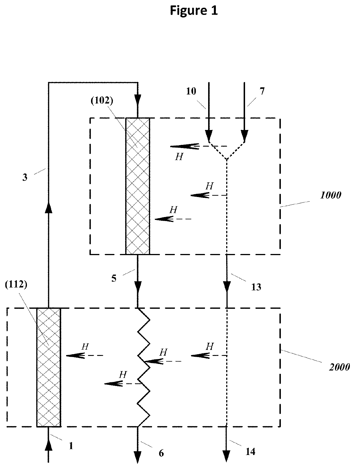
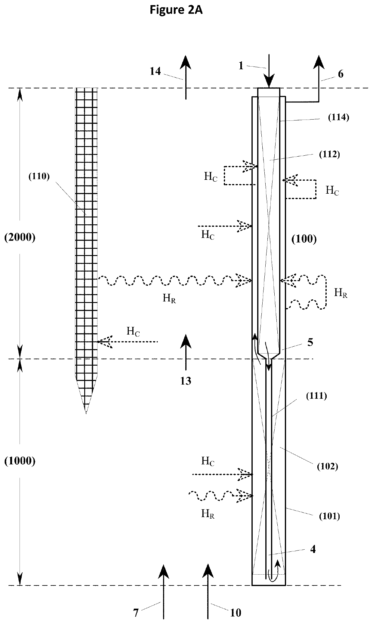
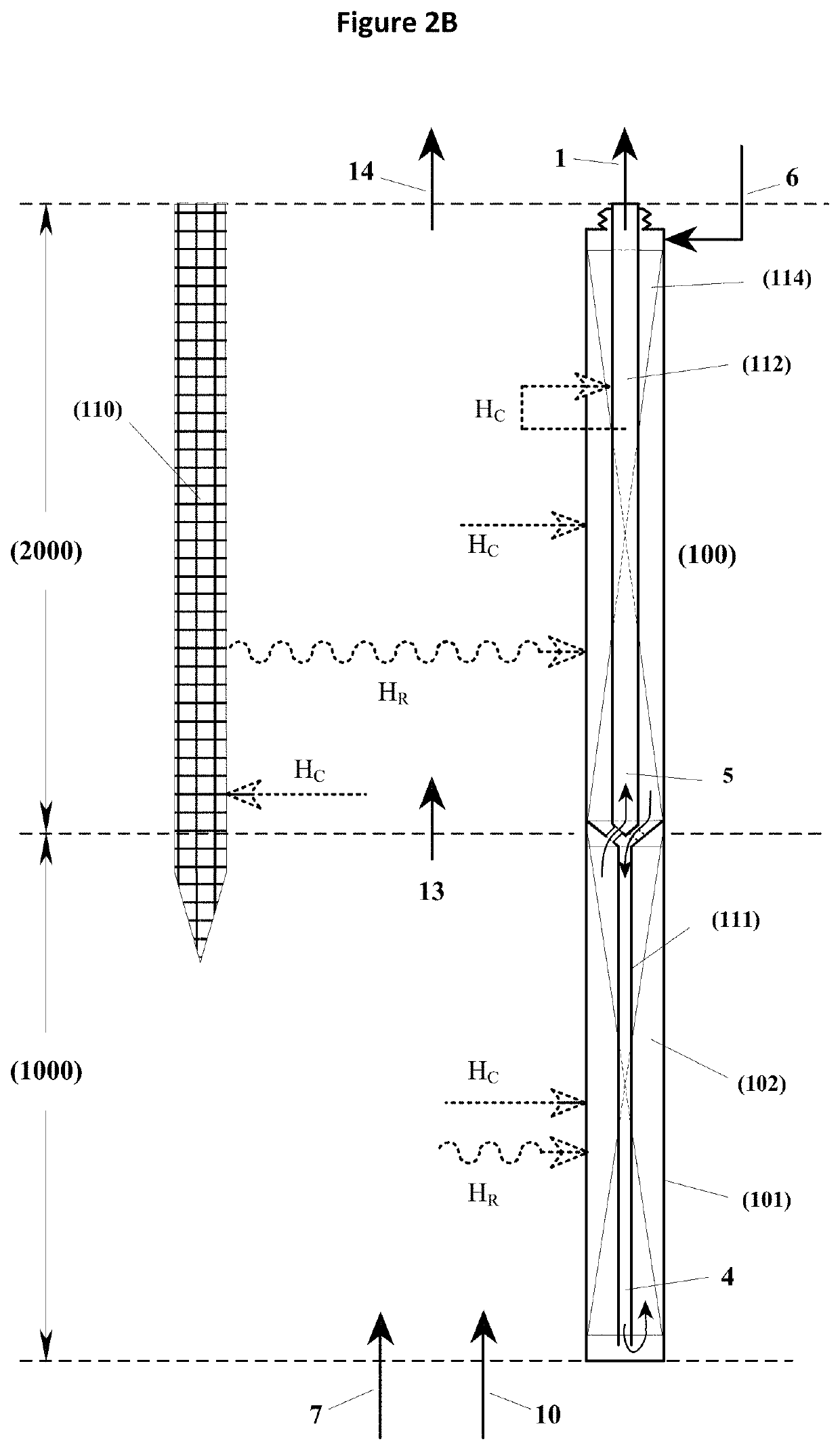
[0111]In the process, combustion air (or other combustion-sustaining medium, for example a mixture of oxygen and CO2) and a fluid fuel are separately fed to a combustion region which also contains therein and throughout conduits containing the second reforming catalyst. Combustion air (or other combustion-sustaining medium) and fuel undertake combustion via one or more burner nozzles within the combustion region.

[0112]Heat may suitably be removed simultaneously and directly into adjacent conduits containing the process gas and second catalyst volume during the combustion process, i.e. heat is transferred not only by “flue gas” (i.e. combustion products) alone but also by their precursors, heated fuel...


PUM


Abstract

A process for steam or dry reforming of hydrocarbons in a reforming reactor, comprising the steps of: (a) passing a feedstock, comprising one or more hydrocarbons together with steam and / or CO2, through a first catalytic zone at an elevated temperature, to form a partly reformed process gas, wherein the first catalytic zone comprises one or more elongate conduits, each containing reforming catalyst; and (b) passing the partly reformed process gas through a second catalytic zone at an elevated temperature, so as to form a reformed gas stream, wherein the second catalytic zone comprises one or more elongate conduits, each containing reforming catalyst; wherein the process further comprises the combustion of a fluid fuel with a combustion-sustaining medium in an exothermic combustion region, to form a hot combustion products stream, wherein the exothermic combustion region is adjacent to and laterally surrounds each of the second catalytic zone elongate conduits.

Description

[0001]The present invention relates to a process for the steam or dry reforming of hydrocarbons, and to apparatus for the steam or dry reforming of hydrocarbons.BACKGROUND TO THE INVENTION[0002]Steam reforming of hydrocarbons, such as methane is well known. Dry reforming of hydrocarbons is also known, whereby CO2 is used to replace all or part of the steam. Although steam reforming is currently more widely used, the present invention is equally applicable to dry reforming. Therefore both processes are contemplated and discussed.[0003]The endothermic reactions occurring in a process for steam hydrocarbon reforming can be described by the following reaction schemes:CH4+H2O=CO+3H2 (−Δ H°298=−206 KJ)CH4+2H2O=CO2+4H2 (−ΔH°298=−165 KJ)[0004]Corresponding reaction schemes can be established for steam reforming of hydrocarbons higher than methane, and likewise for dry reforming where CO2 is the reactant rather than H2O.[0005]These steam reforming reactions occur in a feedstock, or process g...

Claims


Application Information

Patent Timeline
IPC IPC(8): C01B3/38B01J8/04B01J8/06
CPCC01B3/382C01B2203/82B01J8/0465B01J8/0469B01J8/048B01J8/0496B01J8/062C01B3/384B01J2208/00212B01J2208/00309B01J2208/00495B01J2208/00504B01J2208/00849C01B2203/0233C01B2203/0244C01B2203/0811C01B2203/0883C01B2203/142B01J8/0457B01J19/006Y02P20/129
Inventor WEEDON, GEOFFREY GERALDWEEDON, JACK GERALD
Owner BIOHYDROGEN TECH LTD
Features
  • Generate Ideas
  • Intellectual Property
  • Life Sciences
  • Materials
  • Tech Scout
  • Unparalleled Data Quality
  • Higher Quality Content
  • 60% Fewer Hallucinations
Learn More