
3D Printed and In-Situ Poled Flexible Piezoelectric Pressure Sensor

a flexible piezoelectric and pressure sensor technology, applied in the field of 3d printed artificial blood vessels, can solve the problems of increasing manufacturing time, long poling time, and difficult poling, and achieve the effect of outstanding piezoelectric responses and better monitoring local physiological signals

Pending Publication Date: 2021-10-21
WISCONSIN ALUMNI RES FOUND
View PDF16 Cites 3 Cited by
  • Summary
  • Abstract
  • Description
  • Claims
  • Application Information

AI Technical Summary

Benefits of technology

This patent describes a new way to 3D print materials that can be used to create sensors or actuators. The method uses an electric field to help the materials align their electrical charges, which makes them sensitive to changes in electricity. The challenge is that traditional methods of 3D printing can require a long process to create these structures, but the new method helps to increase the poling time, which means the materials can take longer to align their charges. This makes it easier to create complex structures with precision and reduces the time required for manufacturing. Overall, this new method expands the range of materials that can be 3D printed and improves the speed and accuracy of additive manufacturing.

Problems solved by technology

Although some attempts have been made to fabricate ferroelectric structures using 3D printing with electromechanical coupling properties, these structures require a long poling time (a process by which a strong electric field is applied across the material) to exhibit acceptable piezoelectricity.
This greatly increases the manufacturing time.
For 3D-printed ferroelectric materials, such as piezoceramics or lead-free materials, poling is difficult because they suffer from high electrical conductivity, high coercive field, or low breakdown strength due to their irregular shape and existence of internal pores.
Thus, it can be difficult to apply a high enough electric field to obtain a preferred domain orientation.
Moreover, the low Curie temperature (the critical temperature where materials lose their spontaneous polarization and ferroelectric state) of ferroelectric materials make it difficult to maintain their ferroelectric phase at the high printing temperatures required to extrude the filament material simultaneously.

Method used


Image

  • 3D Printed and In-Situ Poled Flexible Piezoelectric Pressure Sensor
  • 3D Printed and In-Situ Poled Flexible Piezoelectric Pressure Sensor

Examples


Embodiment Construction

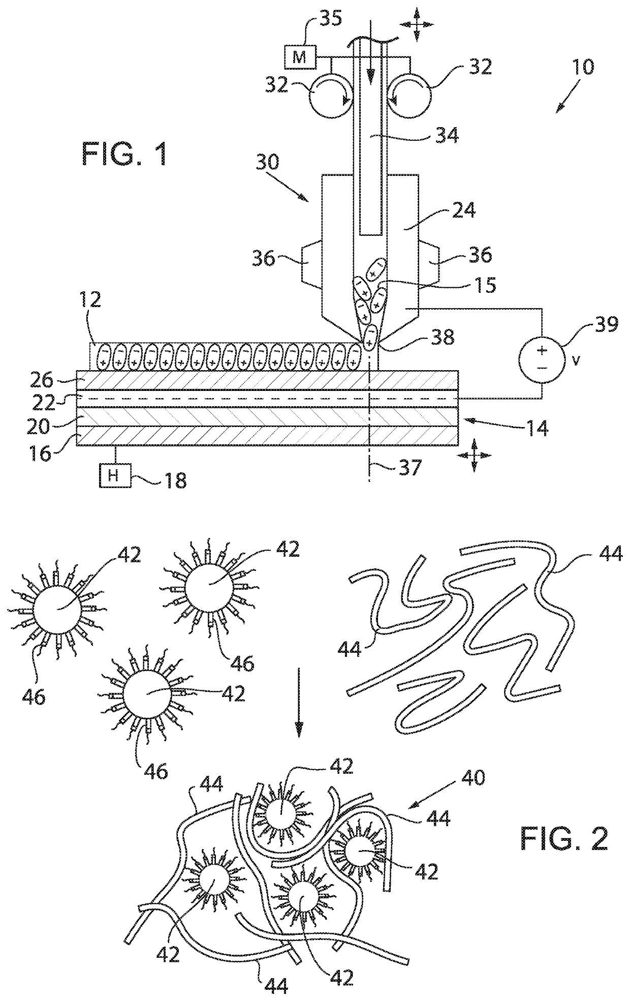
[0047]Referring to FIG. 1, a 3D printing system 10 of the present invention for fused deposition modeling (FDM) may be used with an electric poling process in the manufacture of piezoelectric substrates 12, for example, that may be used to manufacture artificial biological systems such as artificial arteries within the body.

[0048]The 3D printing system 10 may include a build plate 14 providing a substantially planar surface on which the extruded molten material is deposited, layer by layer, during 3D printing. The build plate 14 may be moved vertically up and down, for example, lowered as the layers are added, and translated in all directions within a plane of the build plate 14 to assist with building the shape of the printed object as understood in the art. The build plate 14 includes multiple layers of materials that are used to heat and / or support the extruded material 15 but also to produce an electric field between the build plate 14 and a print nozzle to pole the extruded mat...


PUM

PropertyMeasurementUnit
Curie temperatureaaaaaaaaaa
forceaaaaaaaaaa
thicknessaaaaaaaaaa

Abstract

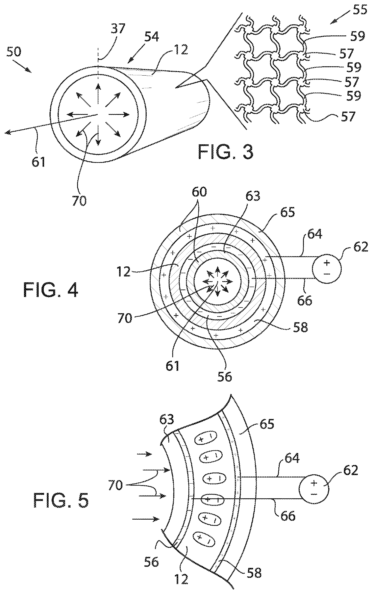
A piezoelectric artificial artery can be 3D printed to provide the real-time precise sensing of blood pressure and vessel motion patterns enabling early detection of partial occlusions. An electric-field assisted 3D printing method allows for rapid printing and simultaneously poled complex ferroelectric structures with high fidelity and good piezoelectric performance. The print material consists of ferroelectric potassium sodium niobite (KNN) particles embedded within a ferroelectric polyvinylidene fluoride (PVDF) polymer matrix.

Description

STATEMENT REGARDING FEDERALLY SPONSORED RESEARCH OR DEVELOPMENT[0001]--CROSS REFERENCE TO RELATED APPLICATION[0002]--BACKGROUND OF THE INVENTION[0003]The present invention relates to a 3D printed piezoelectric material suitable for use as a transducer, and more particularly, a 3D printed artificial blood vessels with piezoelectric response for real-time blood pressure sensing.[0004]Vascular replacement is a common surgical procedure for repairing clot-obstructed or non-functional blood vessels in the treatment of coronary disease, stroke, and limb-threatening ischemia. About 450,000 prosthetic vascular graft implantations have been conducted annually in the United States.[0005]Biomimetic vascular grafts are created with heterogeneous properties close to those of native tissues and precisely matching the anatomy of the individual, allowing for patient-specific implants. However, 40-60% of vascular grafts still fail within the first year of implantation, which results in morbidity and...

Claims


Application Information

Patent Timeline
Patent Type & Authority Applications(United States)
IPC IPC(8): H01L41/277G01L9/08H01L41/37H01L41/333B33Y80/00
CPCH01L41/277G01L9/08B33Y80/00H01L41/333H01L41/37B29C64/118B29C64/209B29C70/62B33Y10/00B33Y30/00B33Y70/10H10N30/852H10N30/8542H10N30/857H10N30/074H10N30/057H10N30/084H10N30/092
Inventor WANG, XUDONGLI, JUN
Owner WISCONSIN ALUMNI RES FOUND
Learn More