
3-d focus-steering lens antenna

a focus steering lens and antenna technology, applied in the field of focusing antennas, can solve the problems of limited field of view, unwieldy system, slowness, etc., and achieve the effects of reducing undesired interference from neighboring structures, fast imaging, and increasing system dynamic range and signal-to-noise ratio

Pending Publication Date: 2021-12-09
CITY UNIVERSITY OF HONG KONG
View PDF0 Cites 1 Cited by
  • Summary
  • Abstract
  • Description
  • Claims
  • Application Information

AI Technical Summary

Benefits of technology

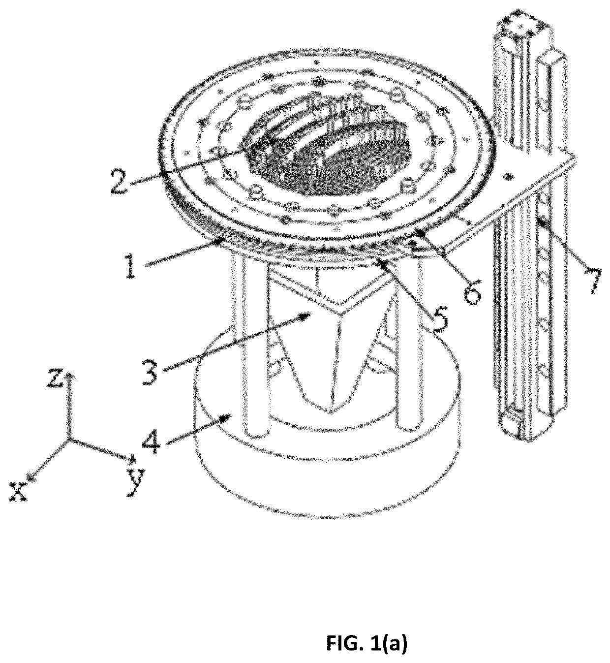
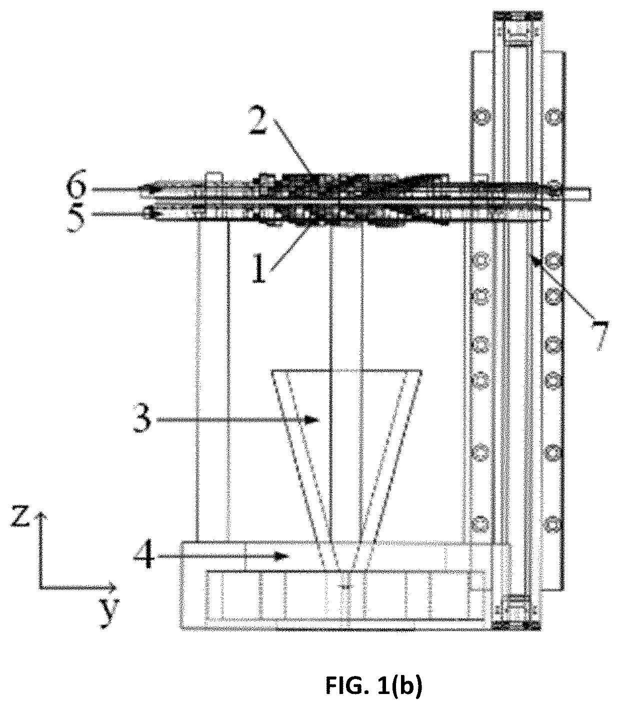
The present invention is about a new type of lens antenna that can focus on objects in three dimensions using millimeter-wave frequencies. The antenna has two lenses that can be rotated to change the focus of the beam. The lenses can also move back and forth to change the length of the focal point. This allows for very fast imaging. The focused beam can help to reduce interference from nearby objects and improve the quality of the image.

Problems solved by technology

The use of conventional bulky refractive / reflective components makes these systems unwieldy, slow, and with limited field of view, for example, 1.1°×1.1°.

Method used


Image

  • 3-d focus-steering lens antenna
  • 3-d focus-steering lens antenna
  • 3-d focus-steering lens antenna

Examples


example 1

Metalens Design:

[0044]Design of Metalens #1 (DDL 1)

[0045]The schematic of Metalens #1 (DDL 1) and its interaction with incident radiation is depicted in FIG. 13(b). A linearly polarized standard pyramid horn (Millitech SGH-03) with a gain of 23 dBi at 0.3 THz is adopted as the feed. The origin of the global coordinate system OG is located at the phase center of the feed horn. The distance between the phase center of the feed horn and Metalens #1 is set as f1=24 mm to provide a proper illumination taper on the aperture of the metalens. Metalens #1 is aimed at transforming the spherical phase front from the phase center of the feed source into a titled plane wave phase front above the aperture of Metalens #1 as shown in FIG. 13(b). The required phase retardation profile φ(x, y) of Metalens #1 is given by:

φ⁡(x,y)=2⁢πλ0⁡[x2+y2+f12-sin⁢θG⁡(x⁢⁢cos⁢⁢φG+y⁢⁢sin⁢⁢φG)](1)

where (x, y) are the global coordinates of each dielectric post, and (θG=20°, φG=0°) is the direction of the transmitted pla...

example 2

Fabrication and Experimental Verification

[0061]Based on the above design a prototype of the 3D focus-steering all-dielectric terahertz metalens was fabricated. 3D printing technology was used to manufacture the two dielectric metasurfaces aiming at simplifying the fabrication process and reduce the cost. FIG. 14(a) shows the photograph of the 3D printed terahertz metalenses. A good profile of the 3D printed metalens is observed. Holes at an angular spacing of 22.5° on the periphery of the metalenses are used for alignment and assembly purpose. A terahertz planar near-field scanning measurement setup was built to measure the performance of the 3D printed focus-steering metalens. A pair of frequency extenders (OML V03VNA2-T / R) is used to extend the operating frequency of the vector network analyzer (Agilent N5245A) up to 220-325 GHz. A pair of DC power sources is utilized as the power supply for the two OML extenders. One extender on a 3-axis translational stage is used to measure the...


PUM


Abstract

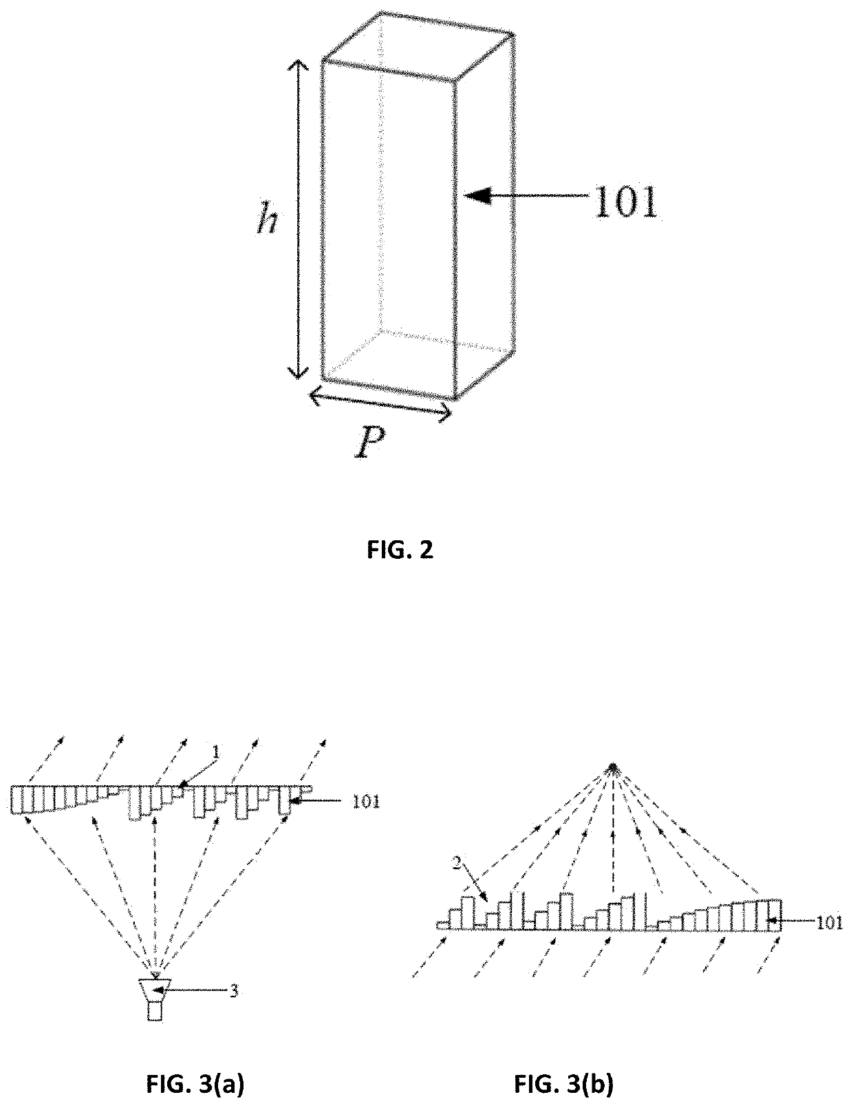
The present invention relates to a novel lens antenna with a 3D near-field focus-steering capability that operates at gigahertz and terahertz frequencies. The novel antenna includes a pair of discrete dielectric lenses fed by a stationary horn source. In-plane synchronous counter-rotation and co-rotation of the lens pair steers its near-field focus radially and azimuthally, respectively, while linear translation of the upper lens moves the focal point longitudinally. The steering focus beam enables fast imaging. In imaging applications, the radiated beam from the novel lens antenna focused in the target area can reduce undesired interference from neighboring structures and increase the system dynamic range and signal-to-noise ratio.

Description

CROSS-REFERENCE TO RELATED APPLICATIONS[0001]This application claims priority from the U.S. provisional patent application serial number 63 / 034,534 filed June 04, 2020, and the disclosure of which is incorporated herein by reference in its entirety.FIELD OF THE INVENTION[0002]The present invention generally relates to focusing antennas generally and, more particularly, to three-dimensional focus-steering lens antennas that may be used in gigahertz and terahertz systems.BACKGROUND OF THE INVENTION[0003]Terahertz radiation, that is, electromagnetic waves in a band from approximately 0.3 to 3 terahertz, has recently emerged as a promising electromagnetic spectral region for various imaging and other applications. Due to features such as wide bandwidth, non-ionizing properties, and penetration capabilities, terahertz radiation-based devices open up new possibilities for non-destructive detection, material characterization, and high-resolution imaging. Focus-steering devices are essentia...

Claims


Application Information

Patent Timeline
IPC IPC(8): H01Q19/06H01Q13/02H01Q3/14
CPCH01Q19/062H01Q3/14H01Q13/02H01Q15/08H01Q15/0026
Inventor CHAN, CHI HOUCHAN, KA FAIWU, GENGBO
Owner CITY UNIVERSITY OF HONG KONG
Learn More