Method for applying a spray to a field

a spray and field technology, applied in the field of spraying methods, can solve the problems of limited operating speed and system inability to carry out location-correct spraying, and achieve the effect of increasing maximum traveling and/or operating speed, reducing the amount of processing time, and being highly simpl

Pending Publication Date: 2021-12-16
ROBERT BOSCH GMBH
View PDF0 Cites 3 Cited by
  • Summary
  • Abstract
  • Description
  • Claims
  • Application Information

AI Technical Summary

Benefits of technology

[0039]In accordance with example embodiments of the present invention, the method of the present invention and the spraying device of the present invention now allow the maximum traveling and / or operating speed to be increased in a highly simple manner during the treatment of a field and, in so doing, to take into account the conflict of aims described at the outset. This is rendered possible, in particular, in that the necessary identification of the rows of plants is indeed carried out in the (entire) monitored field section, but the determination of the plant value is carried out only in a (smaller) specified evaluation portion, that is, in a subsection of the monitored field section. Accordingly, the image processing is divided up into two parallel processing paths having different image sizes. Due to the lower number of pixels in the image for determining the plant value, the necessary processing time therefore decreases. Secondly, by appropriately positioning the evaluation portion in the field section (away from the camera), the reaction path relevant to the application capability may be increased. The two factors, lower processing time and increased reaction path, increase the maximum possible traveling and / or operating speed.
[0040]Furthermore, in this connection, it is advantageous that no classification of the plants and / or plant objects is necessary. Instead, the present invention makes use of the fact that the cultivated plants are grown in plant rows and the weeds and grasses are distributed nonuniformly on the field. Therefore, the present invention defines a plant region including the row of plants, as well as a weed region; by definition, all plants in the plant region being regarded as cultivated plants, and all plants in the weed region being regarded as plants to be treated, in particular, weeds. The predefined spray is then applied to the weed region on the basis of an ascertained plant value, without classification or selection of the plants, and also irrespective of the grouping of the plants.
[0041]It is advantageous for the position of the specified evaluation portion in the monitored field section to be selected in such a manner, that in the direction of travel of the spraying device, the specified evaluation portion has a greater reaction path x, in particular, a maximum reaction path x, with respect to a spray region, that is, to the edge of a spray region of the following spray nozzle, in comparison with the monitored field section, or is positioned essentially centrally in the monitored field section. In this case, a spray region is to be understood as the region of the field, which is treatable / reachable and / or treated / reached by the spray / spray jet from the spray nozzle. This means that in other words, the spray region is a spraying surface or spray coverage. The spray region is a function of, inter alia, the spray characteristic of the spray nozzles. Using the first alternative, reaction path x and, therefore, the reaction time, may be maximized (at the expense of the image resolution). In the case of higher standards of accuracy, the highest image quality may be attained by the second alternative, since the lens aberrations are smallest in the center of the image, in which case reaction path x is increased, as well.
[0042]It is also advantageous for the position of the specified evaluation portion in the monitored field section to be selected as a function of a traveling speed of the spraying device, in particular, selected in such a manner, that a maximum image resolution in the specified evaluation portion results at a given traveling speed of the spraying device. Due to this measure, the maximum and / or most effective image resolution possible is selected in an automated manner as a function of the traveling speed, which means that the accuracy of the method, in particular, of ascertaining the plant value, may be increased.
[0043]In addition, it is advantageous for the step of identifying the at least one row of plants to be repeated (immediately) after a defined route section is covered, and / or (immediately) after defined time intervals, and / or (immediately) after irregular time intervals, and / or (immediately) after an executed change of direction of the agricultural spraying device in a defined angular range, and / or if computing time is available, in order to identify the current position of the rows of plants again. The change of direction may be, in particular, turning and / or a turning event, which means that the step of identifying the at least one row of plants is repeated immediately after the execution and / or completion of the change in direction and / or the turning event. The change of direction may be detected, in particular, with the aid of an acceleration sensor. In this connection, during these time intervals, that is, between the steps of defining the at least one row of plants for the step and / or steps of defining the at least one plant region, it is particularly advantageous for the position of the at least one row of plants in the direction of travel of the spraying device to be extrapolated or assumed to be constant. That is, in other words, the step of identifying the at least one row of plants is not carried out continually, that is, not for each step of the defining of the plant region and the weed region, and of the ascertaining of the plant value. Therefore, on one hand, the step of identifying the at least one row of plants and, on the other hand, the steps of defining the plant region and the weed region and ascertaining the plant value, are each carried out in parallel, asynchronous “processing paths.” This action is possible, since the analyzed variables change on two different time scales: While the plant value, e.g., the degree of coverage, is an extremely local variable, for which strict requirements regarding its latency are set (“decision to spray”), the position of the rows of plants is approximately constant. Changes in the position of the rows of plants are produced only from the driving motion and / or camera motion, inaccuracies in the sowing, as well as the ground profile. These changes take place on comparatively long time scales and are also of a gradual nature. Thus, the positions of the rows of plants in the direction of travel may be extrapolated or assumed to be constant, and may be used as an input for the determination of the plant value in the parallel “processing path.” This allows time, that is, computing time, for the image records and image processing, as well as internal communication time, to be reduced, which means that the total reaction time may be shortened or reduced further.

Problems solved by technology

If more time is necessary for image recording, image processing, internal communication times, nozzle and / or valve control, and flight time of the spray, then the system is not able to carry out locationally correct application.
In this connection, there is a conflict of aims between the detection of the rows of plants, the quality of which increases with the length of the image portion in the direction of travel, and the detection of weeds, in which images that are high-resolution and as small as possible are required, in order to obtain sufficient ground resolution and minimize the processing time, which means that ultimately, the operating speed is limited.

Method used


Image

  • Method for applying a spray to a field
  • Method for applying a spray to a field
  • Method for applying a spray to a field

Examples


Embodiment Construction

[0050]In the description below of preferred exemplary embodiments of the present invention, the same or similar reference numerals are used for the elements that are shown in the different figures and function similarly, in which case a repeated description of these elements is omitted.

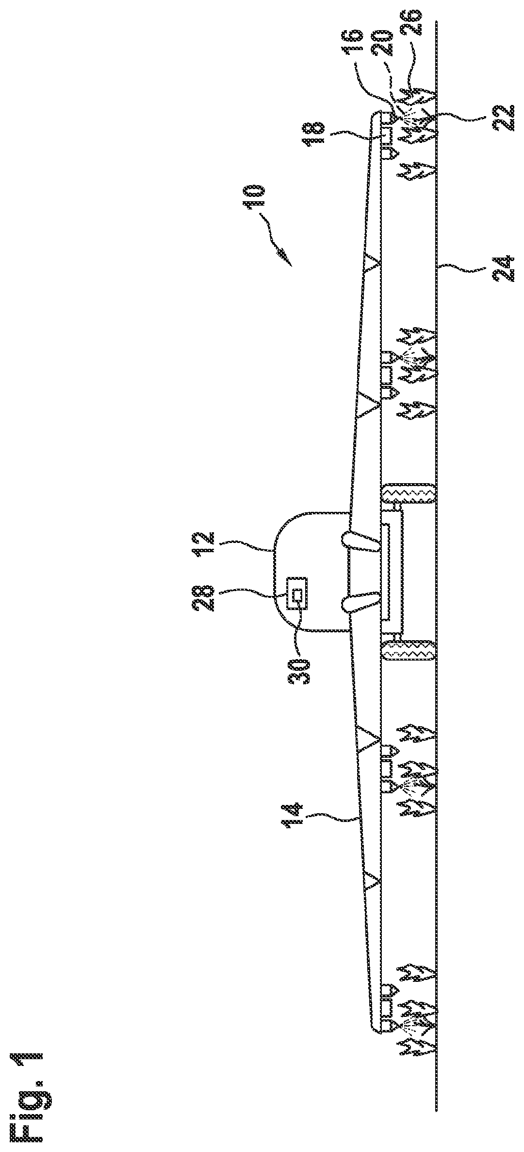
[0051]A schematic representation of an agricultural spraying device, the entirety of which is denoted by reference numeral 10, is shown in FIG. 1.

[0052]Agricultural spraying device 10 takes the form of a field sprayer 10. Field sprayer 10 is positioned on a mobile land vehicle 12, which takes the form of a towing vehicle 12 or tractor 12.

[0053]Agricultural spraying device 10 includes a spray boom 14. Spray nozzles 16 and optical detection units 18 are situated on spray boom 14. Spray nozzles 14 are designed to apply a spray 20 to weeds 22 of an agricultural plot. Optical detection units 18 take the form of optical cameras 18. Optical cameras 18 each include a filtering unit for extracting a color port...


PUM


Abstract

A method for applying a spray to a field using an agricultural spraying device. The method includes: monitoring a field section of the field having plants, using an optical and/or infrared detection unit; identifying at least one row of plants in the monitored field section using a processing unit; using the processing unit, defining a plant region including the at least one identified row of plants in a specified evaluation portion of the monitored field section, using the at least one identified row of plants and a weed region different from the plant region; ascertaining a plant value of the weed region in the specified evaluation portion of the monitored field section using the processing unit; and applying the spray to the weed region of the specified evaluation portion as a function of the ascertained plant value, using spray nozzles of the agricultural spraying device.

Description

FIELD[0001]The present invention relates to a method for applying a spray, in particular, a crop protection chemical, to a field with the aid of an agricultural spraying device, as well as to an agricultural spraying device. The present invention also includes a control unit and a computer program.BACKGROUND INFORMATION[0002]Algorithms for detecting rows of plants are available. In most cases, the basis for them are camera shots, which have been taken from a field machine. These shots are taken at sharp angles of inclination and show an image portion that is as large as possible, in order to simplify the detection of plant rows as much as possible.[0003]In addition, methods for detecting and classifying weeds are available, which are executed, using small, high-resolution images, and preferably at no angle of inclination, in order to obtain sufficient image resolution for detecting small plant objects.[0004]Together with the traveling speed, the geometric distance between the monito...

Claims


Application Information

Patent Timeline
Patent Type & Authority Applications(United States)
IPC IPC(8): A01M7/00A01M21/04G05B15/02
CPCA01M7/0089G05B15/02A01M21/043
Inventor SEITZ, PETERHOUIS, NICOLASFALCK, TILLMANN
Owner ROBERT BOSCH GMBH
Why Eureka
Try Eureka