Vape devices, including cartridges, tablets, sensors, and controls for vape devices, and methods for making and using the same

a technology of vape devices and control devices, which is applied in the direction of tobacco and other directions, can solve the problems of no control, no control, no control to prevent the use of the vape device by anyone other than the user of the vape device, etc., and achieve the effect of reducing the amount of payload, and improving the flow of payload

Pending Publication Date: 2021-12-30
CANOPY GROWTH CORP
View PDF4 Cites 45 Cited by
  • Summary
  • Abstract
  • Description
  • Claims
  • Application Information

AI Technical Summary

Benefits of technology

[0031]A vape device in accordance with another exemplary embodiment of the invention described herein comprises a housing, an atomizer positioned in the housing, and a payload reservoir positioned in the housing. The housing comprises a first end and a second end, wherein a longitudinal axis of the housing extends between the first end and the second end. The payload reservoir is defined at least in part by a reservoir side wall comprising a first end positioned adjacent the atomizer and a second end. The reservoir side wall slopes toward the atomizer from the second end of the reservoir side wall to the first end of the reservoir side wall when the housing is positioned so that the longitudinal axis is generally horizontal. The reservoir side wall preferably improves the flow of payload to the atomizer to keep the atomizer bathed in the payload and reduce the amount of payload that is wasted in the reservoir.
[0032]A vape device in accordance with another exemplary embodiment of the invention described herein comprises a housing comprising a first end and a second end. A longitudinal axis of the housing extends between the first end and the second end. The vape device is configured so that the housing orients itself in a predetermined position when the housing is placed on a generally horizontal surface and the longitudinal axis is generally horizontal. The housing preferably is able to orient itself in a predetermined position so that a payload within the housing is able to flow into contact with an atomizer to keep the atomizer bathed in the payload and reduce the amount of payload that is wasted in the reservoir.
[0033]A vape device in accordance with another exemplary embodiment of the invention described herein comprises a housing, a tray that is positioned in the housing, an atomizer positioned in the housing, and a flexible circuit board. The housing comprises a first end and a second end. A longitudinal axis of the housing extends between the first end and the second end. The housing defines an inlet, an outlet positioned adjacent the second end of the housing, and an air flow chamber positioned between the inlet and the outlet. The tray comprises a first section that defines a recess and a second section that defines a payload reservoir positioned adjacent the second end of the housing. The tray comprises a first side positioned adjacent the housing and a second side. The atomizer is in fluid communication with the payload reservoir. A flexible circuit board is positioned adjacent the second side of the tray in the recess defined by the tray. The flexible circuit board and tray preferably make manufacturing of the vape device more efficient and consistent.
[0034]A vape device in accordance with another exemplary embodiment of the invention described herein comprises: a housing defining an inlet, an outlet, and an air flow chamber positioned between the inlet and the outlet; an atomizer positioned in the air flow chamber; a capacitive sensor positioned in the air flow chamber between the atomizer and the outlet; and a sensor measurement circuit connected to the capacitive sensor. The atomizer is configured to heat and vaporize a payload to generate a vaporized payload. The capacitive sensor defines a measurement cavity within the air flow chamber. The sensor measurement circuit is configured to directly or indirectly measure a capacitance of the capacitive sensor when the vaporized payload passes through the measurement cavity. The vape device is preferably configured to accurately determine the dosage based on a measured capacitance of vaporized payload in a measurement cavity of the vape device. This vapor measurement system is beneficial to both medicinal patients and recreational users because they will be able to accurately measure their dosage to obtain desired effects in a repeatable fashion.

Problems solved by technology

Conventional vape devices such as these provide: no control as to the ramping up and / or down of power applied to the heating element; no control as to the metering of how much vapor is produced when the switch is closed; no control as to how particular fluids or oils are to be heated to produce vapor; and no control to prevent unauthorized use of the vape device by anyone other than the user of the vape device.
Further, storing the vape device or cartridge in a particular orientation can be cumbersome.
When the atomizer heats the fluid, the fluid may leak through the air intake path out of the cartridge or vape device.
Further, if the user inhales before the fluid is vaporized, the user may inhale spurts of oil droplets.
However, this introduces a fibrous material to the vape device or cartridge that can burn and be contaminated in the production environment.
The process of wrapping the atomizer with a layer of cotton is fine detailed work that requires such a high degree of manual dexterity that the factory workers use their bare fingers to perform the procedure, which is unhygienic.
These small circular openings trap air bubbles that prevent flow of the fluid to the atomizer, which is commonly known as “air-lock.” The positioning of the circular openings also frequently leads to oil waste within the cartridge or vape device.
In particular, there may be differences in thermally induced chemical reactions or metabolic transformations between the vaping of dry material and the vaping of fluid that may affect the user in a different manner.
This process is relatively cumbersome and inconvenient for the user and often leads to loss of material through spillage and / or sticking to the grinder.
Further, if the dry material is cannabis, it is difficult to control the dose of active compounds consumed due to variations of the cannabinoid profile from strain to strain, batch to batch, and based on the location where the plant is grown.
While there are a few conventional vape devices that attempt to determine the dosage of a vaporized payload, they use inaccurate methods that offer poor dose metering performance, e.g., using the known volume and strain of the payload being vaporized to assume the dosage.
As such, medicinal patients are unsure of the dosage that they have taken at any given time, which limits the repeatability and efficacy of the drug's effects.
Also, recreational users may experience different effects (desirable and undesirable) depending on dosage.
However, this documentation is easily separated from the cartridge and is likely to be discarded, lost, or potentially even tampered with.
If the user possesses multiple cartridges, it is possible that he or she will misidentify the cartridges and may not get the expected experience from a particular cartridge.
Further, a medical user may not receive the desired relief of his or her symptoms with a particular cartridge.
If a conventional cartridge is installed on a control assembly capable of supplying too much power, there is the possibility of the cartridge being damaged, the payload being burnt, or the user being injured.
Conventional vape devices that use a two-pin connector to join a cartridge and control assembly are not able to control the atomizer temperature across all operating modes (e.g., low to high airflow, low to high ambient temperature, battery voltage, etc.).
Using these parameters, a rudimentary form of temperature control can be achieved, but it is very limited in accuracy.
In particular, there is generally no accounting for air flow, ambient temperature, and / or current atomizer temperature, which can dramatically impact the atomizer temperature when in use.
The issue of localized atomizer temperature is particularly problematic with dried cannabis products because the atomizer surface area in contact with the payload is large in comparison to liquid payloads.
Further exacerbating the problem is the fact that not all of the cannabis payload is directly in contact with the atomizer due to the volume of cannabis used (typically on the order of 1 cubic centimeter).
In this case, it is likely that the payload in direct contact with the atomizer may begin to burn while the payload farther from the atomizer will remain in an area of low heat and potentially not vaporize.
This leads to smoke and wasted product, neither of which is desired.
If the air is too hot, the payload will burn.
However, these methods are limited with respect to the level of authentication and access control that may be desired for a vape device.

Method used


Image

  • Vape devices, including cartridges, tablets, sensors, and controls for vape devices, and methods for making and using the same
  • Vape devices, including cartridges, tablets, sensors, and controls for vape devices, and methods for making and using the same
  • Vape devices, including cartridges, tablets, sensors, and controls for vape devices, and methods for making and using the same

Examples


second embodiment

of Vape Device

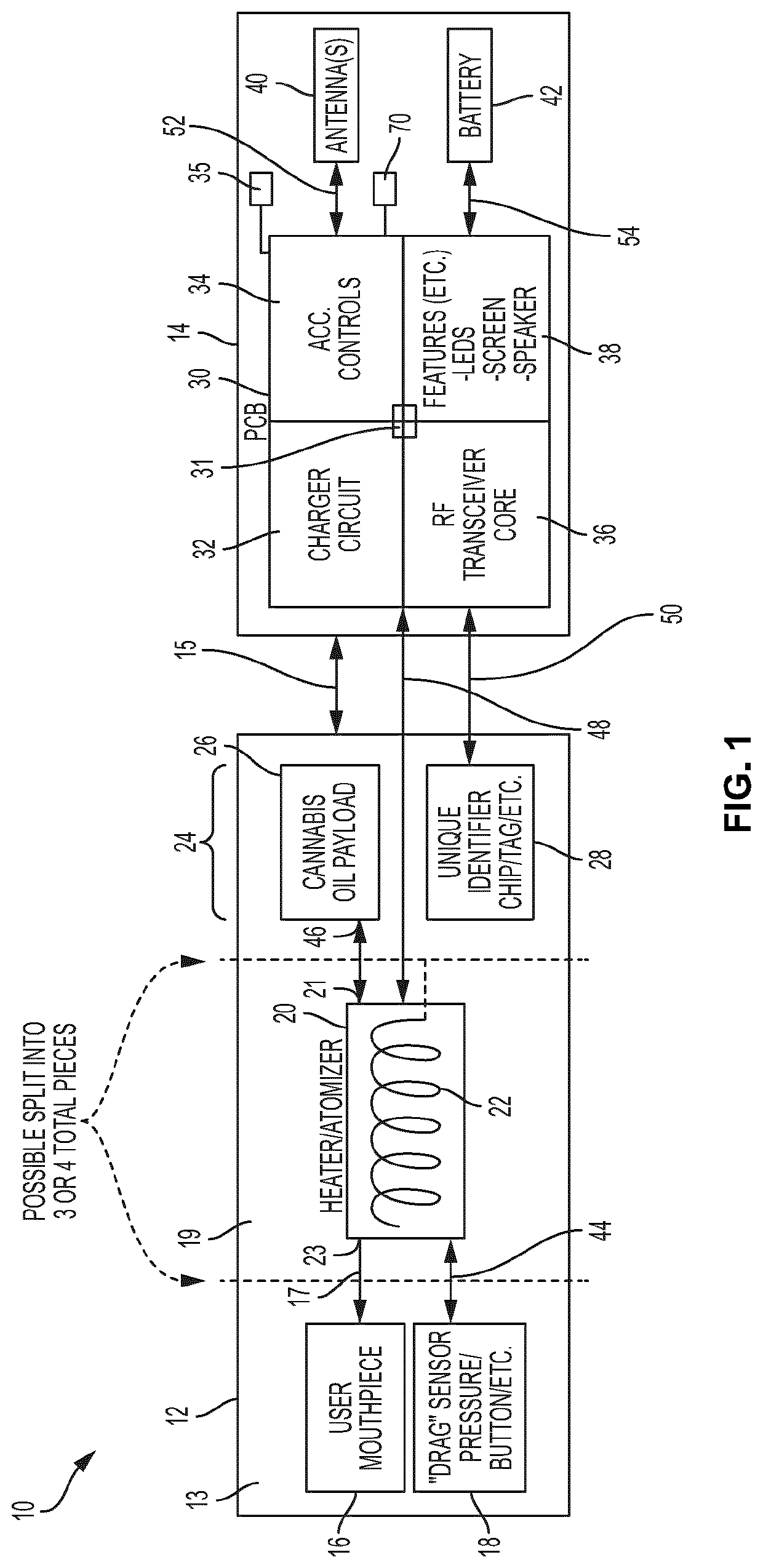
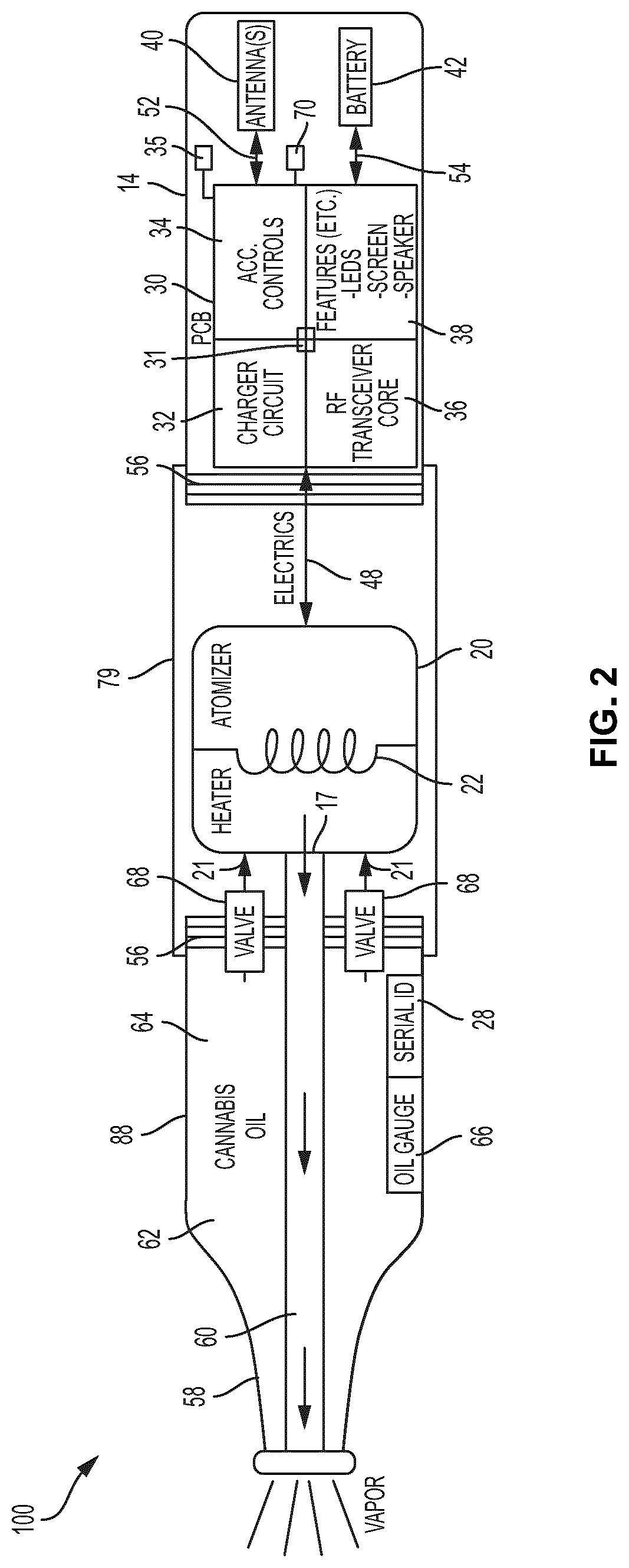
[0169]Referring to FIG. 2, another embodiment of vape device 100 is shown. In some embodiments, vape device 100 can comprise control assembly 14, atomizer assembly 79 and mouthpiece assembly 88 operatively coupled together in that order using mechanical connection means 56 to join the subassemblies together. Mechanical connection means 56 can comprise one or more of threaded connection means, magnetic connection means and friction or press-fit connection means, and any of the connection means 15 described above, including 510 threaded connectors. In some embodiments, mouthpiece assembly 88 can comprise a mouthpiece 58 in communication with the outlet of atomizer 20 via conduit 60. Mouthpiece assembly 88 can further comprise a payload reservoir 62 that can be filled with a payload 64 that may be liquid or oil. The payload 64 can flow from payload reservoir 62 to inlet 21 of atomizer 20 via one or more valves 68. In some embodiments, mouthpiece assembly 88 can comprise I...


PUM


Abstract

Vape devices and methods of operating the same to prevent unauthorized use, allow for remote, centralized storage of operational settings associated with unique payload identifiers, and to optimize operation based on historical usage data, real-time operating conditions, and/or user information. Vape devices for vaporizing dry material and methods of operating the same. Tablets comprising dry material for vaporization and methods of making and using the same. Vape devices and cartridges to improve flow of a fluid payload to an atomizer and to prevent leaking and spurting of the fluid payload, including vape devices and cartridges that pressurize the fluid payload. Vapor measurement systems to determine dosage based on a measured capacitance of vaporized payload. A two-lead communication system that enables the communication of a plurality of electrical signals between a control assembly and cartridge. A cartridge temperature control system that provides localized temperature control for the cartridge.

Description

CROSS-REFERENCE TO RELATED APPLICATIONS[0001]This application is based on and claims priority to U.S. patent application Ser. No. 15 / 921,144, filed on Mar. 14, 2018, U.S. Provisional Application Ser. No. 62 / 642,805, filed on Mar. 14, 2018, U.S. Provisional Application Ser. No. 62 / 642,825, filed on Mar. 14, 2018, U.S. Provisional Application Ser. No. 62 / 661,306, filed on Apr. 23, 2018, U.S. Provisional Application Ser. No. 62 / 668,380, filed on May 8, 2018, U.S. Provisional Application Ser. No. 62 / 680,057, filed on Jun. 4, 2018, U.S. Provisional Application Ser. No. 62 / 696,930, filed on Jul. 12, 2018, U.S. Provisional Application Ser. No. 62 / 696,937, filed on Jul. 12, 2018, U.S. Provisional Application Ser. No. 62 / 696,943, filed on Jul. 12, 2018, U.S. Provisional Application Ser. No. 62 / 733,286 filed on Sep. 19, 2018, and U.S. Provisional Application Ser. No. 62 / 797,694 filed on Jan. 28, 2019 each of which is incorporated herein by reference in its entirety.BACKGROUND OF THE INVENTION...

Claims


Application Information

Patent Timeline
Patent Type & Authority Applications(United States)
IPC IPC(8): A24F40/57A24F40/42A24F40/53A24F40/51A24F40/60A24F40/65
CPCA24F40/57A24F40/42A24F40/65A24F40/51A24F40/60A24F40/53
Inventor DAVIS, STEPHENPENNEY, STEVENPICCOLI, JOHNPOPPLEWELL, PETERSTEWART, ANDREWWONG, MICHAEL
Owner CANOPY GROWTH CORP
Why Eureka
Try Eureka