Ffwn clean energy power plant

a clean energy and power plant technology, applied in the field of ffwn, can solve the problems of low overall efficiency, low efficiency of the power plant, and low efficiency of the plant, and achieve the effects of increasing the flow rate, increasing the efficiency and power output of the power plant, and increasing the pressure of the liquid

Pending Publication Date: 2022-01-13
VON BARGEN EDWARD
View PDF8 Cites 3 Cited by
  • Summary
  • Abstract
  • Description
  • Claims
  • Application Information

AI Technical Summary

Benefits of technology

[0015]In view of the inherent limitations of the prior art, embodiments of the present invention that use compressed gas—preferably compressed air—to dramatically increase the pressure of the liquid used throughout the system will have several advantages: (1) Except for minor losses, which may require the periodic addition of additional liquid, the level of the liquid within the system will largely be unchanged. (2) The compressed air will essentially be trapped within an airtight and watertight storage tank while the power plant is in operation so it can constantly be used to apply pressure to the liquid in the storage tank. (3) After the initial setup of the power plant, any compressed air that may be added periodically will preferably be produced with surplus power that might have otherwise gone to waste. (4) The overwhelming pressure provided by the compressed air constantly pushing on the liquid in the storage tank, which will make it possible for powerful pumps to dramatically increase the flow rate velocity of the liquid flowing through multiple turbines within a coiled section of pipe, will dramatically increase the efficiency and power output of the power plant. (5) The dramatic increase in the efficiency and power output of the power plant will make it possible to produce large quantities of surplus electric power.

Problems solved by technology

Unfortunately, due to the high cost of building and maintaining an OTEC power plant, as well as the low overall efficiency of an OTEC power plant of 2% to 3%—which typically uses nearly as much electricity as it produces to run the pumps and convert back to liquid form the vaporized low boiling point fluid that is used to drive a turbine / generator and ultimately produce net electric energy—it has not been a commercial success.
However, because solar is only good for about 4 hours of power on average daily globally, and wind for less than 6 hours of power on average daily globally, doing so would be very expensive.
However, the brine water does not reach the surface because it has greater density than the original salt water.
Also, none of the above mentioned patents that use compressed air to increase the pressure of a liquid within a tank produce more electric power than they consume.
This is largely due to the highly inefficient process of producing the compressed air, how the pressure of the compressed air decreases as it drives the water out of the tank (for instance, if the area occupied by the compressed air is doubled as it drives the water out of the tank the pressure of the compressed air will be cut in half), how the tanks containing pressurized water for the purpose of producing electric power repeatedly need to be refilled, and how the pressurized water is used to produce a limited amount of electric power by driving a single energy producing device.

Method used


Image

  • Ffwn clean energy power plant
  • Ffwn clean energy power plant
  • Ffwn clean energy power plant

Examples


Embodiment Construction

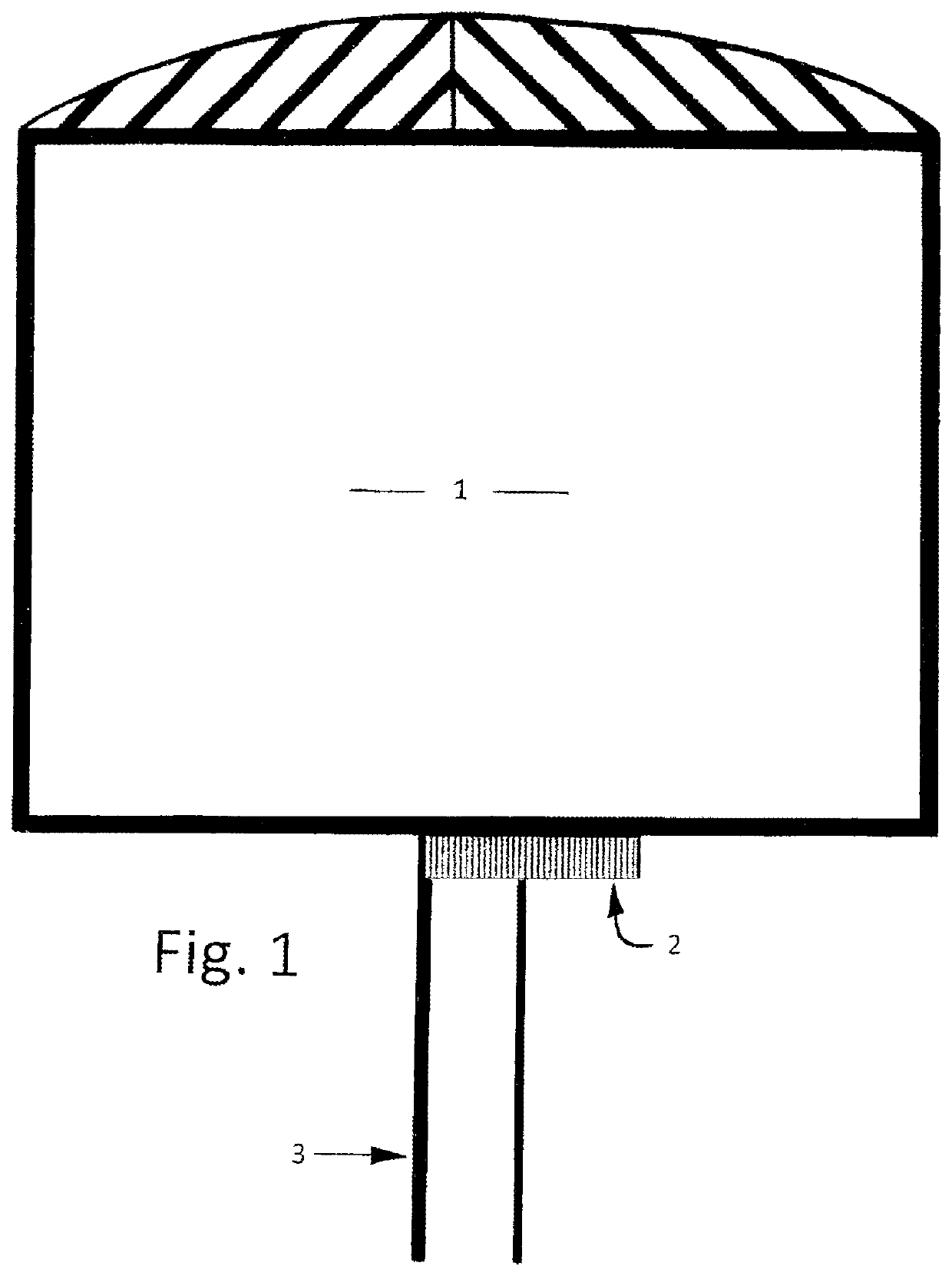
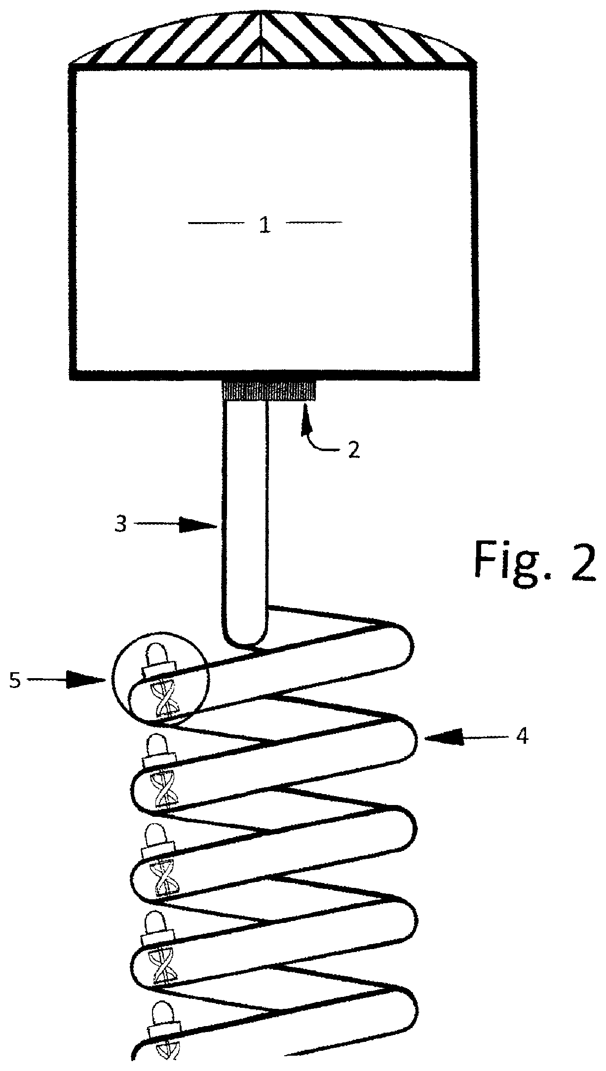
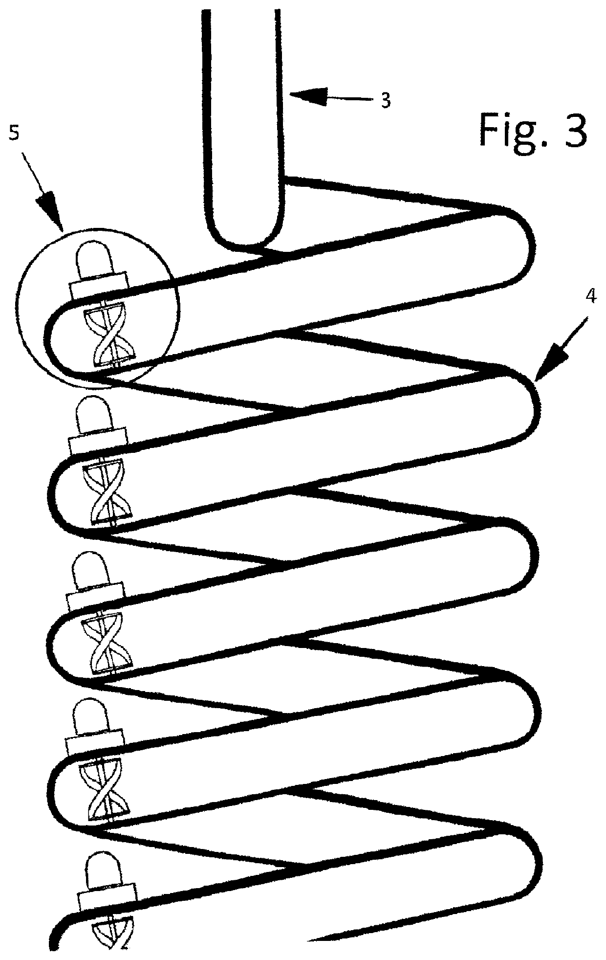
[0115]None of the parts in the drawings are to scale or are necessarily in proportion to those that may be found in an operational unit of the present invention. In some instances, certain features may be exaggerated in order to better illustrate and explain the present invention. All the parts shown are only intended to clearly convey the concepts and basic principles involved. Also, for clarity and simplicity's sake, some connections and structural supports and other components, as well as mechanical and electrical components and controls, are not shown. Furthermore, in the case of commonly known or generally understood parts that may be used in the successful operation of the invention, simple geometric shapes may be used at times to help depict them. The drawings are numbered consecutively beginning with 1 (example FIG. 1), as are the corresponding parts within the different views (examples: 1, 2, 3, 4, 5 . . . ).

[0116]As described previously, storage tank will relate in general...


PUM


Abstract

Gravity and hydrostatic pressure are natural forces that have considerable force generating capabilities which can make significant contributions during the operation of a FFWN 24/7/365, baseload, 100% clean energy power plant. When these natural forces are combined with compressed air in the upper part of an elevated storage tank containing a liquid and the partial vacuum created by powerful pumps to produce a targeted water flow rate velocity of about 31.3 m/s through the entire length of a coiled section of pipe containing one or more helical turbines in each coil that are connected to an external generator, the electricity produced during a power producing cycle by all the turbines/generators when combined will be considerably more than the power ultimately consumed by the pumps to return the highly pressurized water in a ground level tank back to the storage tank utilizing a return tank and simple water displacement.

Description

CROSS REFERENCE TO RELATED APPLICATION[0001]This patent application is related to and claims the benefit of provisional application Ser. No. 63 / 048,880, filed on Jul. 7, 2020, which is incorporated herein by reference.BACKGROUND[0002]The present invention relates to FFWN (Fossil Fuel's Worst Nightmare) clean energy power plants, and more particularly, to 24 / 7 / 365, baseload, one-hundred percent clean energy power plants.[0003]Hydro-electric power plants and nuclear power plants are two current types of baseload electric power plants that do not require the burning of fossil fuels. Historically, there have been many attempts by inventors to invent other types of clean energy power plants that could be used to replace natural gas and coal-fired power plants as baseload electric power sources. Up until now, one of the few with the ability to produce a fairly significant amount of surplus electric power has been an ocean thermal energy conversion (OTEC) power plant.[0004]An OTEC power pl...

Claims


Application Information

Patent Timeline
Patent Type & Authority Applications(United States)
IPC IPC(8): F03B13/10H02K7/18
CPCF03B13/10F05B2220/706F05B2220/32H02K7/1823F03B17/005F05B2220/20F05B2240/40Y02E10/20Y02E10/30Y02E60/16
Inventor VON BARGEN, EDWARD
Owner VON BARGEN EDWARD
Why Eureka
Try Eureka