
Additive manufacturing process

a manufacturing process and additive technology, applied in the field of additive manufacturing process, can solve the problems of high dental prosthesis cost, high maintenance cost, and high cost of computer-controlled milling and grinding machines, and achieve the effects of low viscosity, high cohesive strength or slump resistance, and increased printing rate of curable compositions

Pending Publication Date: 2022-02-03
DENTSPLY SIRONA INC
View PDF1 Cites 0 Cited by
  • Summary
  • Abstract
  • Description
  • Claims
  • Application Information

AI Technical Summary

Benefits of technology

The present invention provides an additive manufacturing process for making dental appliances with excellent dimensional accuracy, aesthetic, and mechanical properties, without requiring extensive manual finishing or surface treatment. This is achieved by using a specific curable composition containing large glassflakes and a shear stress inducing discharge orifice, which reduces the dynamic viscosity of the curable composition, allowing for faster printing without compromising resolution and dimensionality. The uncured structure of the curable composition has high cohesive strength and slump resistance, allowing for multiple layers to be printed and additional support structures to be omitted. The cured composite composition containing large glassflakes provides excellent mechanical properties including flexural strength. This additive manufacturing process can be used for the rapid chairside or laboratory preparation of dental appliances.

Problems solved by technology

However, computer-controlled milling and grinding machines are costly and require careful maintenance resulting in considerable maintenance costs.
Additionally, most of the block material is lost in the subtractive milling and grinding process making the dental prosthesis cost high.
However, for the purpose of many dental applications, the mechanical properties or chemical resistance of the solidified thermoplastic materials are not acceptable.
While such methods allow for high-speed and affordable 3D-printing, their demand for low viscosity resins (typically <6 Pas) limits suitable materials to low filler contents (<1%).
Consequently, the printed physical objects deliver insufficient mechanical properties (flexural strength / E-modulus), limiting their application, to non-permanent restorations, surgical guides or splints.
Moreover, SLA or DLP require extensive manual finishing such as excess resin removal using organic solvents, removal of support structures, as well as finishing and polishing.
Therefore, conventional 3D printing processes cannot be used chairside for the preparation of single unit permanent dental restorations such as crowns, inlays, onlays and veneers.
However, the use of a composite material in an extrusion or jetting step during additive manufacturing is problematic due to particle induced clogging of the fine nozzles required for high resolution printing.
Therefore, the cohesive strength or consistency of the uncured composite material of WO 2016 / 142323 is low, and layers may tend to flow.
Accordingly, although the mechanical properties of a dental appliance are improved by the use of a composite material over conventional thermoplastic polymers, the dimensional accuracy, the production rate and mechanical properties of the process according to WO2016 / 142323 cannot compete with the dimensional accuracy, the production rate and mechanical properties of conventional subtractive processes.
Even in the preparation of small dental appliances, the limited strength of the uncured material, the limited cohesive strength of the cured material and the required manual finishing prevent the process of WO2016 / 142323 from being useful for single unit permanent dental restorations such as crowns, inlays, onlays and veneers.

Method used


Image

  • Additive manufacturing process
  • Additive manufacturing process
  • Additive manufacturing process

Examples


examples

[0240]Milling of Glassflakes by Means of Pearl Mill:

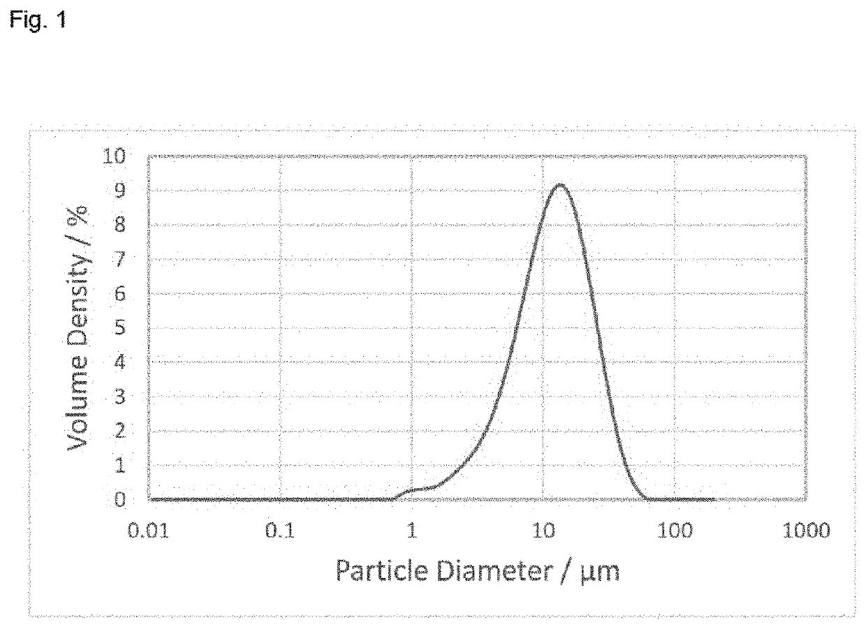
[0241]The grinding container of the mill (Dyno-mill Multi Lab, Willy A. Bachofen AG Maschinenfabrik) was filled with 450 mL grinding beads (soda-lime glass, 0.75-1 mm). In a storage tank 100 g ECR glassflakes GF350nmM (from Glassflake Ltd., Leeds, England) without surface functionalization were dispersed in 1.5 L water. A homogeneous dispersion was maintained by continuous stirring. The dispersion was pumped by a peristaltic pump into the grinding container and returned from the mill outlet into the storage tank. Milling was stopped once the particle diameter D3,50 and D3,99 reached the desired values.

[0242]Washing of Glassflakes:

[0243]When adding unwashed glassflakes into a dental composition, greyish pastes were obtained. For better aesthetical results, the glassflakes may be washed prior to coating. For washing, the glassflakes may be stirred in twice the amount of 2.5% hydrochloric acid for half an hour, and then filtered off a...


PUM

PropertyMeasurementUnit
diameter D3aaaaaaaaaa
particle diameteraaaaaaaaaa
diameteraaaaaaaaaa

Abstract

An additive manufacturing process comprising:(a) providing a curable composition comprising:(i) a filler comprising glassflakes having a diameter D3,99 as determined by light scattering in the range of from 5 to 150 μm; and(ii) one or more curable compounds;(b) controlling an apparatus to form an object by using the curable composition, whereby the curable composition passes a discharge orifice having a minimum diameter Φmin,wherein the ratio of the minimum diameter of the discharge orifice to the diameter D3,99 of the glassflakes (Φmin / D3,99) is in the range of 2 to less than 10; and wherein the median diameter D3,50 of the glassflakes is larger than the thickness of the glassflakes.

Description

FIELD OF THE INVENTION[0001]The present invention relates to an additive manufacturing process. Moreover, the present invention relates to a cartridge for a 3D printer, and a kit-of-parts comprising a plurality of specific cartridges of the present invention. Finally, the present invention relates to a curable dental composition for use in the additive manufacturing process of the present invention.[0002]The additive manufacturing process of the present invention may be used for the preparation of a wide range of solid objects. However, particular advantages are available in the rapid chairside or laboratory preparation of dental appliances having excellent dimensional accuracy, aesthetic and mechanical properties and which avoids extensive manual finishing.BACKGROUND OF THE INVENTION[0003]Dental appliances such as restorations are conventionally manufactured by subtractive milling and grinding processes using milling and grinding machines controlled by a software for machining a co...

Claims


Application Information

Patent Timeline
Patent Type & Authority Applications(United States)
IPC IPC(8): A61K6/77B33Y80/00B33Y70/10A61K6/887A61K6/17A61C5/77
CPCA61K6/77B33Y80/00B33Y70/10B29K2509/08A61K6/17A61C5/77A61K6/887B29C64/10B29C64/209B33Y10/00B33Y70/00A61C13/0019C08K3/40C08K7/00C08K2201/003B29C64/259B29C64/112B29C64/118
Inventor NOERPEL, STEPHANIETIGGES, THOMASWALZ, UWEWEBER, CHRISTOPH
Owner DENTSPLY SIRONA INC
Learn More