Lubrication-free centrifugal compressor

a centrifugal compressor and lubrication-free technology, which is applied in the direction of non-positive displacement fluid engines, radial flow pumps, pump components, etc., can solve the problems of high maintenance requirements of the lubrication system, the most bulky of the four types of alternative compressors, and the most mechanical wear of the above mentioned components, etc., to achieve high efficiency, high electric frequency, and high speed

Pending Publication Date: 2022-02-17
SMART E LLC
View PDF7 Cites 0 Cited by
  • Summary
  • Abstract
  • Description
  • Claims
  • Application Information

AI Technical Summary

Benefits of technology

[0020]This compressor uses, as the driving source, an axial flow and permanent magnet electric motor operating synchronically at high speed and high electric frequency. Said motor operates efficiently at high speed, since it has less ferromagnetic core in its stator than the equivalent radial flow motors. In fact, this motor may work efficiently even with no ferromagnetic core in its stator. The compressor impeller is directly coupled to the motor on a single axis, forming a single mobile part of the device. The high efficiency of the axial flow motor and the absence of speed multiplying gears give this invention higher reliability and global energy efficiency over the current art.
[0021]The motor-impeller rotating assembly is supported by a combination of magnetic radial bearings and electrodynamic thrust (or axial) bearings, such that there is no mechanical contact with the stator. Said bearings use permanent passive magnets, therefore they do not require control systems, sensors or external energy supply. This gives the invention a higher operating simplicity and reliability than the one of the current art.
[0022]The complete rotor, formed by the motor-impeller assembly and the magnetic and electrodynamic bearings, is located inside a waterproof chamber pressostatically linked to the stator of the compressor and flooded by the same process gas. In this way the use of mechanic seals is avoided as well as the subsequent wear by friction, which gives this invention the feature of requiring less maintenance than other similar current art equipment.
[0023]By not requiring lubrication for bearings, gears or seals, the device of this invention does not use auxiliary systems for cooling, filtering, separation or feeding of lubricants. This allows the invention for higher simplicity and smaller size than other similar devices of the current art.

Problems solved by technology

The main drawback of this technology lays in the intensive maintenance required by the lubrication system, which is needed to assure the sealing between plungers and cylinders, the integrity and water tightness of valves and to avoid damage in bearings.
However, all the above mentioned components suffer from mechanical wear and should be periodically replaced, even when they are maintained in optimal lubricant conditions.
Due to the number of mechanisms involved, alternative compressors are the most bulky of the four types mentioned (with low specific power).
In opposition, they have fewer mobile components than the alternative compressors; therefore, the mechanical wear is less relevant as regards maintenance.
The major drawback lays in the lubrication system requirements, which should be maintained free of solid particles and should be constantly cooled.
The problems faced by these compressors are related to the high speed at which their impellers should spin (typically between 20,000 and 100,000 rpm).
Gear assemblies are a key component, both due to the mechanical wear and the loss of energy they imply.
Another problem appears on the seals that keep the process gas isolated from the atmosphere.
The above mentioned complexities have limited the use of centrifugal compressors to large scale applications.
The main disadvantage appearing on the use of high speed radial flow motors lays on the great amount of ferromagnetic material present on stators.
The high electric frequency used at high speed implies huge losses of energy in said cores as parasitic currents and magnetic hysteresis.
The complexity shown by the AMB lays in the need for an axis position sensor set and an active control electronic system which externally energizes and commands the bearings.
In the event of an energy interruption of the control system, the rotating axis may lose support and contact the stator spinning at high speed and producing significant and permanent damage.

Method used


Image

  • Lubrication-free centrifugal compressor
  • Lubrication-free centrifugal compressor
  • Lubrication-free centrifugal compressor

Examples


Embodiment Construction

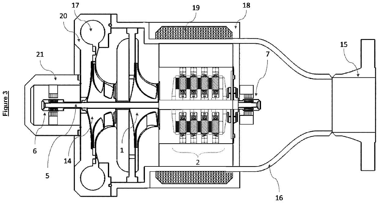
[0029]The present invention is a compact device for gas compression driven by an axial flow synchronous electric motor with no use of any kind of lubricants.

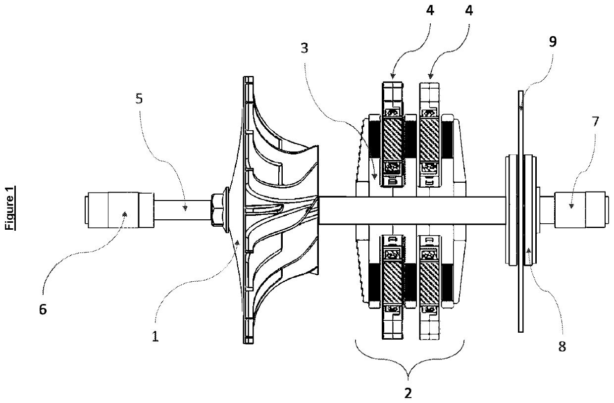
[0030]FIG. 1 shows the single mobile piece of the motor-impeller rotating assembly (hereinafter, the rotor). Said rotor has a centrifugal impeller 1 in charge of delivering kinetic energy to the process gas. In the embodiment of FIG. 1 only one impeller is shown but more than one may be used. Said impeller is mounted on an axis 5 and fixed thereto. If more than one impeller is used, all of them may be mounted on and fixed to the same axis.

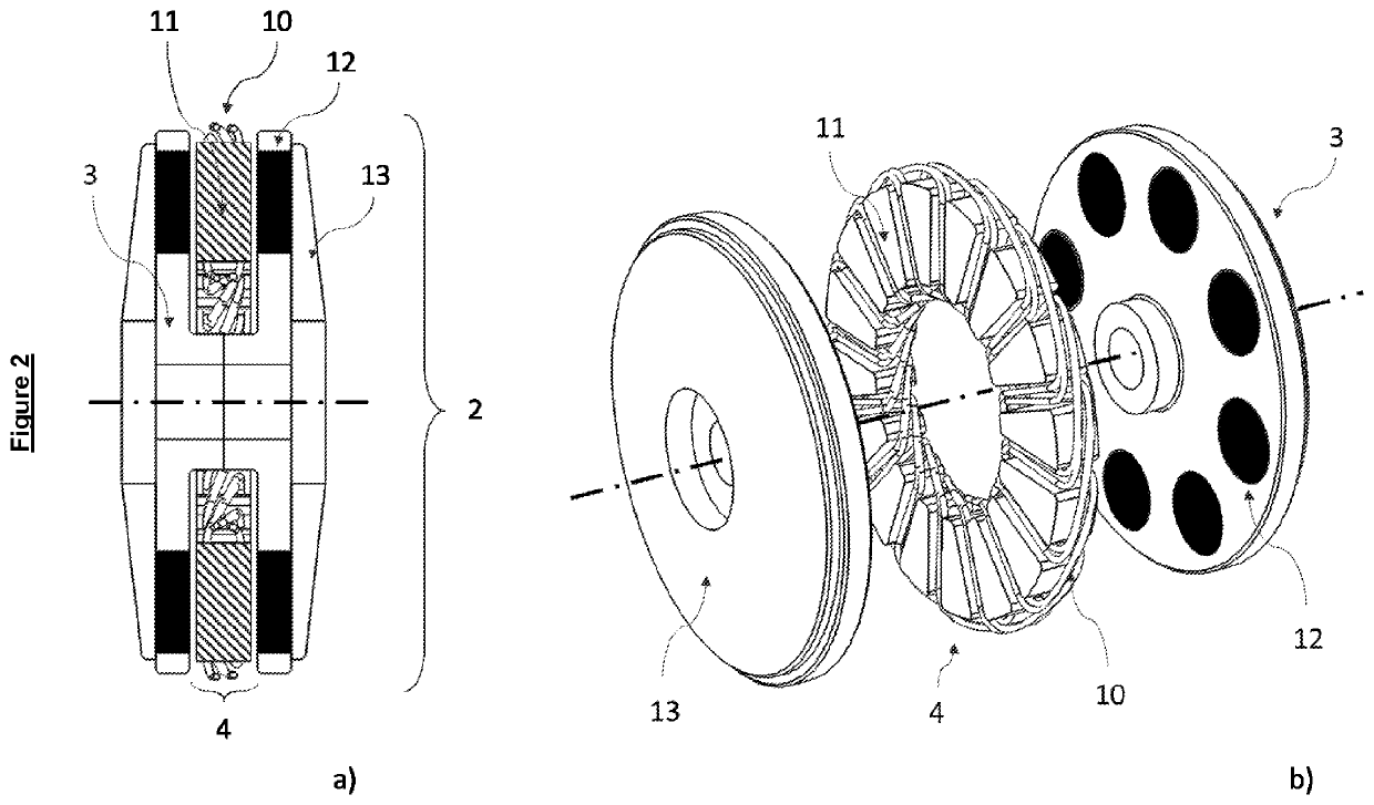
[0031]An axial flow synchronous and permanent magnet electric motor 2 is formed by a stationary stator section and a rotating section. The stator section of said motor contains the coils, different auxiliary pieces for support and may optionally contain part of the ferromagnetic core. This section may be formed by one or more assemblies located between assemblies of a rotating section. In the e...


PUM


Abstract

A gas compression compact device comprised of: a) one or more centrifugal compressors; and b) a high speed axial flow permanent magnet synchronous electric motor. The electric motor and the compressor are directly coupled on a single axis and supported by passive magnetic and electrodynamic bearings, free of lubrication. The equipment does not use mechanic seals since the rotor is placed inside the pressure containment of the gas. The equipment does not require auxiliary systems for cooling, filtration, separation or feeding of lubricant fluids.

Description

CROSS-REFERENCE TO RELATED APPLICATION[0001]This application claims the benefit of U.S. provisional application No. 62 / 769,323, filed 19 Nov. 2018, which is hereby incorporated by reference as though fully set forth herein.FIELD OF THE INVENTION[0002]The present invention pertains to the field of gas compression equipment. In particular, the present invention refers to compact electric devices or equipment which use centrifugal compressors to increase a gas pressure.BACKGROUND[0003]Gas compression by mechanical means is currently carried out through different technologies which are widely spread and tested from some years ago. Among the most used methods are centrifugal, axial, alternative and screw compressors.[0004]Alternative, or piston, compressors are similar in construction to internal combustion engines. A piston or plunger displaces longitudinally in an alternate manner inside a cylinder, against which a series of seals are located. A set of valves allows the entrance of gas...

Claims


Application Information

Patent Timeline
Patent Type & Authority Applications(United States)
IPC IPC(8): F04D29/041F04D25/06F04D17/10
CPCF04D29/0413F04D17/10F04D25/06F04D25/0653F04D17/122F04D29/058
Inventor ECHENIQUE, ESTEBAN JOSÉLABOLLITA, SANTIAGO
Owner SMART E LLC
Why Eureka
Try Eureka