
Planar transformer employing insulating structure for performance improvement

Pending Publication Date: 2022-02-24
LEE JOO YEOL
View PDF0 Cites 1 Cited by
  • Summary
  • Abstract
  • Description
  • Claims
  • Application Information

AI Technical Summary

Benefits of technology

The present invention allows for the miniaturization of a transformer while ensuring a minimum insulation distance of 7 mm between the primary and secondary sides. This is achieved by fitting the insulating block and base to the transformer, reducing resistance and manufacturing costs while maintaining efficiency. The transformer provides electrical stability and a firm coupling between the insulating block and base without requiring additional adhesive.

Problems solved by technology

On the other hand, the transformer has been developed to achieve miniaturization and lightweight, and to obtain the electrical stability in the operation process of the transformer, accordingly, a given distance between a primary part and a secondary part has to be maintained, which undesirably causes limitations in the miniaturization of the transformer.
In this case, the thickness of the transformer is reduced, but the whole region of the transformer is increased (that is, the lengths of the coil patterns formed on a printed circuit board are increased), thereby failing to achieve perfect miniaturization of the transformer.

Method used


Image

  • Planar transformer employing insulating structure for performance improvement
  • Planar transformer employing insulating structure for performance improvement
  • Planar transformer employing insulating structure for performance improvement

Examples


first embodiment

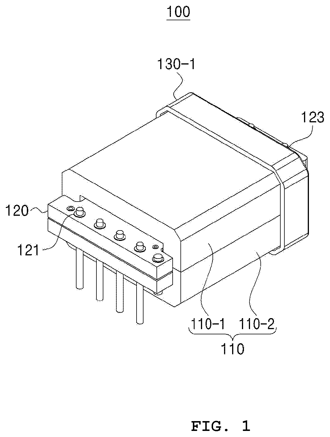
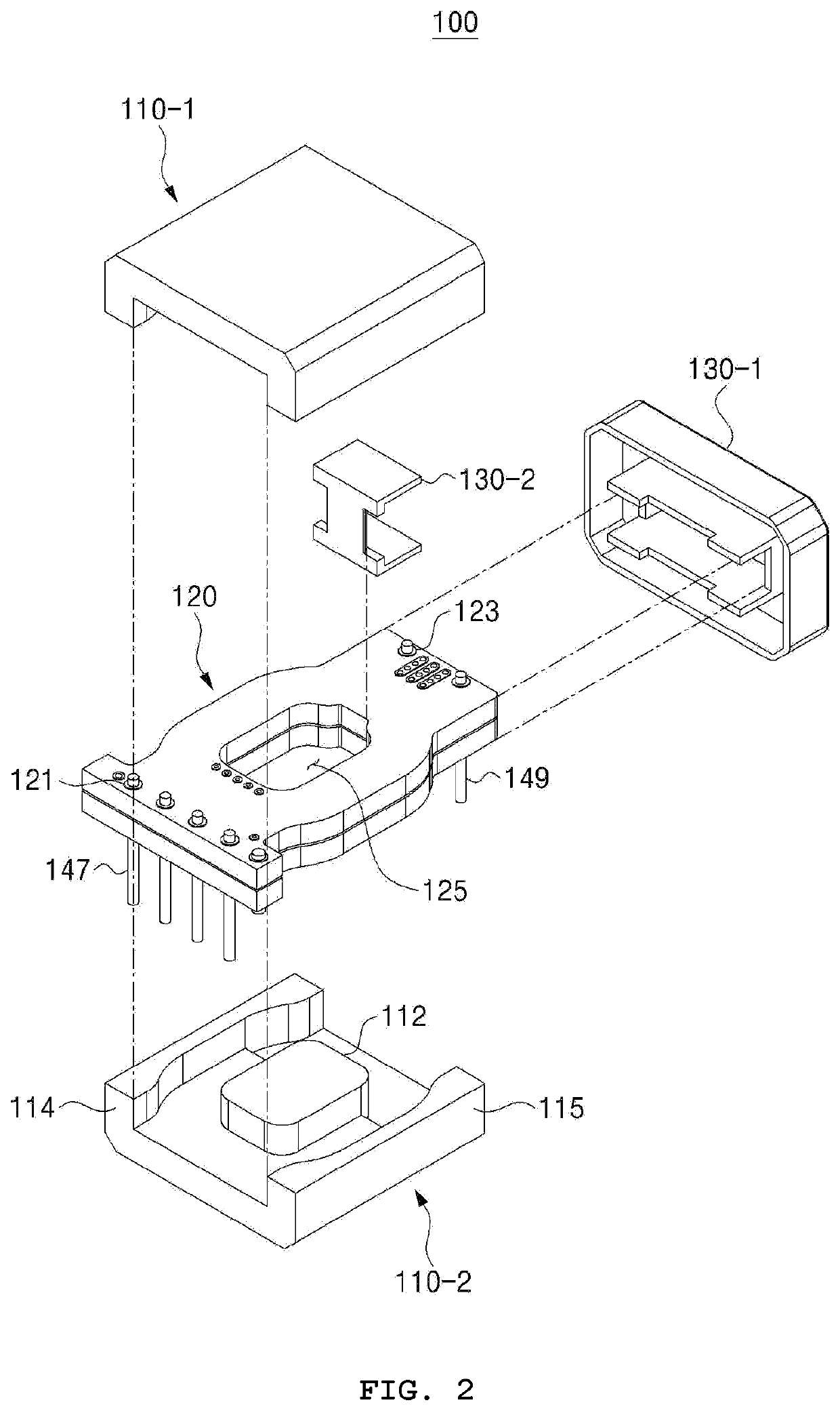
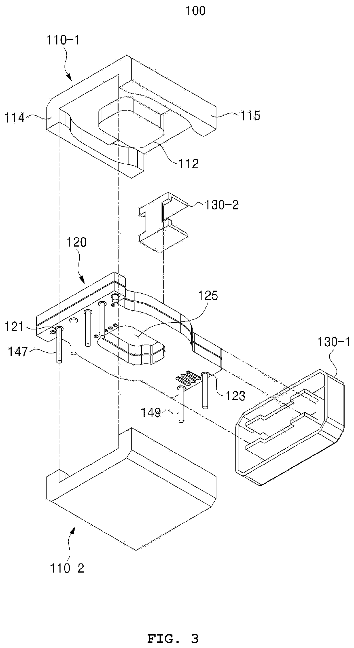
[0071]Referring to FIGS. 1 to 3, the planar transformer 100 (hereinafter, referred to as transformer) employing an insulating structure for performance improvement according to the present invention includes a pair of ferrite cores 110 constituted of an upper core 110-1 and a lower core 110-2 that are electromagnetically coupled to each other, a printed circuit board 120 disposed in an internal space formed by the pair of ferrite cores 110, and an insulating block 130-1 and an insulating base 130-2 for ensuring an insulation distance between the pair of ferrite cores 110 and the printed circuit board 120.

[0072]The pair of ferrite cores 110 forms the internal space in which a conversion process of stepping up or down the voltage inputted through the transformer 100 is carried out. To do this, when the pair of ferrite cores 110 is vertically cut down, the upper core 110-1 and the lower core 110-2 each include a first outer leg 114, a middle leg 112, and a second outer leg 115 to thus ...

second embodiment

[0109]Up to now, the explanation of the components of the transformer 100 according to the present invention has been given. According to the present invention, the insulation distance t between the pair of ferrite cores 110 and the secondary via holes 123 is ensured by means of the insulating block 130-1 and the insulating base 130-2 that are fitted to each other, thereby minimizing the lengths of the coil patterns formed on the printed circuit board 120 and achieving the miniaturization and performance improvement of the transformer 100.

[0110]Hereinafter, the structures of the insulating block 130-1 and the insulating base 130-2 capable of ensuring the insulation distance will be explained.

[0111]FIG. 10 is a top view showing the transformer 100 according to the second embodiment of the present invention, FIG. 11 is a sectional plan view showing the transformer 100 according to the second embodiment of the present invention, FIG. 12 is a sectional view taken along the line A-A′ of ...


PUM


Abstract

A planar transformer employing an insulating structure for performance improvement includes: a pair of ferrite cores (110) including an upper core (110-1) and a lower core (110-2); a printed circuit board (120), which is disposed between the pair of ferrite cores (110), one end of which has primary via holes (121) electrically connecting primary coil patterns, and the other end of which has secondary via holes (123) electrically connecting secondary coil patterns; an insulating block (130-1) for receiving one side of the pair of ferrite cores (110); and an insulating base (130-2) disposed in the pair of ferrite cores (110) and fittedly coupled to the insulating block (130-1), wherein the insulating block (130-1) and the insulating base (130-2) receive a given region of the printed circuit board (120) at one side at which the secondary via holes (123) is disposed.

Description

TECHNICAL FIELD[0001]The present invention relates to a planar transformer employing an insulating structure for performance improvement, and more particularly, to a planar transformer employing an insulating structure for performance improvement that is capable of ensuring an insulation distance between a primary part and secondary via holes of a printed circuit board through a separate insulating block, while not extending the lengths of the coil patterns formed on the printed circuit board.BACKGROUND ART[0002]A charger for charging a battery for a mobile device receives a commercial voltage supplied to a house, converts the received voltage into a voltage adequate for the charge of the battery, and charges the battery. In this case, the commercial voltage supplied to the house is an alternating current voltage of 220 V, and the voltage for the charge of the battery is 5 V. Accordingly, the charger steps down the commercial voltage of 220 V to voltages 5 / 9 / 12 / 20 V, converts the st...

Claims


Application Information

Patent Timeline
IPC IPC(8): H01F27/28H01F27/32H01F27/26H05K1/16H05K1/11
CPCH01F27/2804H01F27/324H01F27/263H05K2201/086H05K1/115H01F2027/2819H05K1/165H01F2027/2809H01F27/266H01F27/306H05K3/0097H05K2201/10303H05K2201/09063H05K1/0298H01F2017/002
Inventor LEE, JOO YEOL
Owner LEE JOO YEOL
Learn More