Method and apparatus for interfacing ion and molecular selecting devices with an ion counter

a technology of ion counter and molecular selection device, which is applied in the field of method and apparatus for interfacing an ion mobility spectrometer (ims) with an ion counter, can solve the problems of low vapour pressure of some explosives, difficult to detect concealed explosives in small quantities, and difficult to achieve low detection threshold of ions

Active Publication Date: 2022-03-03
ANCON TECH
View PDF2 Cites 0 Cited by
  • Summary
  • Abstract
  • Description
  • Claims
  • Application Information

AI Technical Summary

Problems solved by technology

The low vapour pressure of some explosives presents challenges to current IMS devices.
An even greater challenge is to detect concealed explosives in small quantities.
The principal disadvantage of the Faraday cup is that the low detection threshold of ions is relatively high, with the limit being set by its amplification circuit and electrical thermal noise.
This prior art method has reached its physical limit in modern IMS devices and cannot be used to improve further the detection sensitivity to the level of extremely low concentrations of ions in gases.
Therefore, it is not possible to connect an IMS directly to an ion counter to detect ions of certain mobility selectively without detecting all the ions passing through the drift tube.
Therefore, as an IMS, it is similarly not possible to connect a GC directly to an ion counter.
A potential problem which was encountered with earlier prototypes of the present apparatus is that there can be a backflow of aerosol tagging particles into the IMS device thereby leading to fouling and malfunction of the IMS device.
Conventional methods of detecting nanoparticles typically involve the use of Condensation Particle Counters which have very poor detection efficiency for particles with diameters below 10nm.
A potential source of inaccuracy in measuring ion concentrations is that the analyte ions may come into contact with the internal surfaces of the tagging chamber and give up their charge.
A potential problem with this arangement is that reagent ions may be formed by ionisation of the carrier gas in the ionisation chamber and such reagent ions may reduce the accuracy of the detection and quantifying of the ions of interest by the individual ion counter device.

Method used


Image

  • Method and apparatus for interfacing ion and molecular selecting devices with an ion counter
  • Method and apparatus for interfacing ion and molecular selecting devices with an ion counter
  • Method and apparatus for interfacing ion and molecular selecting devices with an ion counter

Examples


example 1

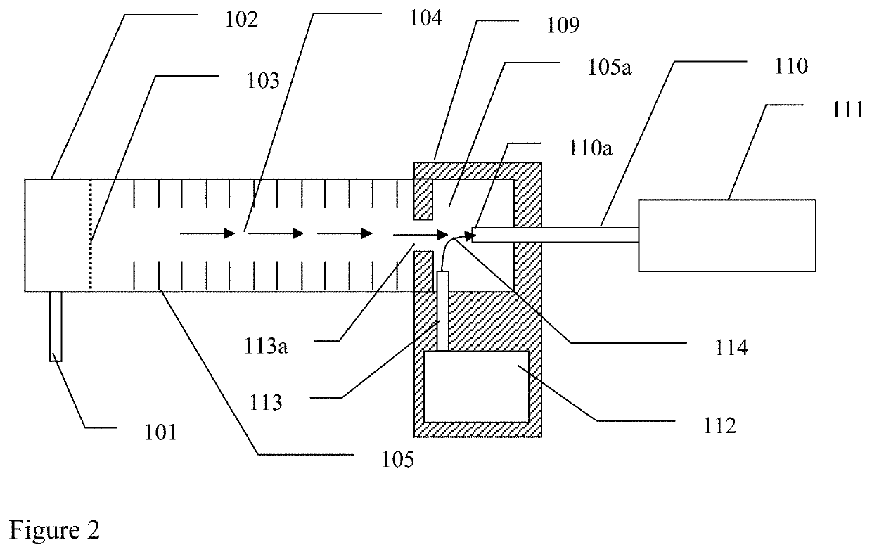
[0195]An IMS as shown in FIG. 3 was made in which the tagging aerosol conduit (213), the extraction conduit (210) and the manifold tube (215) were manufactured from stainless steel tubes.

[0196]As an alternative to stainless steel tubes and conduits, other materials such as other metals and alloys, e.g. brass, aluminium, glass or plastic, can be used. Preferably the conduits and tubes are made from electrically conductive materials or non-conductive materials with an electro-conductive layer on the surface. Such a layer can be made by metal plating, vacuum deposition or painting with a conductive paint.

[0197]The second BN gate (209) was made from gold plated brass shim with dimensions identical to the dimensions of the first BN gate (203). The NMT detector (211) including the tagging aerosol generator (212) was built as disclosed in U.S. Pat. No. 7,372,020, but then the tagging particle generator (212) was removed from the IIC and integrated into the interface. The second BN gate con...

example 2

[0199]An ion counter of the type disclosed in U.S. Pat. No. 7,372,020 was interfaced with an IMS lonscan 400B (Barringer) using an embodiment of the present invention shown in FIG. 2. The stainless steel conduit (110) was manufactured from a tube of 2 mm ID. Tagging aerosol particles of 100 nm diameter were generated from sebacate by an aerosol generator of the type disclosed in U.S. Pat. No. 7,372,020. The flow rate of aerosol particle tags in the tag conduit (113) was 0.2 l / min−1. The flow rate of tagged ions in the conduit (110) was 0.2 l / min−1.

[0200]An example of data recorded with the above-described IMS-NMT (IMS-ion counter) is shown in FIG. 4.

example 3

[0201]Table 1 contains data for another example demonstrating an increase in sensitivity. In this example, an Excellims MA3100 IMS was interfaceds with an NMT detector. Here replacement of the Faraday cup detector by the NMT ion counter resulted in the reduction of the Limit Of Detection at 90% confidence (LOD90) by ˜10 times for both TNT and RDX [2,3].

TABLE 1ASTM LOD90 results for IMS-NMT with theExcellims MA3100 and IMS-Faraday cup.LOD90 (ASTM)LOD90 (ASTM)SubstanceIMS-NMTIMS-Faraday cupTNT38 pg327 pgRDX8.6 pg  95 pgPETN32 pgNot detectable

Embodiments of the Invention

[0202]The following are embodiments of the invention:

[0203]1. An apparatus comprising:[0204](i) an ion selecting device;[0205](ii) an individual ion counting device;[0206](iii) an interface device integral with the ion selecting device and being located downstream of an ion separating chamber of the ion selecting device, the interface device comprising a tagging particle generator and a tagging chamber, the tagging cham...


PUM

PropertyMeasurementUnit
detection timeaaaaaaaaaa
diameteraaaaaaaaaa
diameteraaaaaaaaaa

Abstract

An apparatus comprising an ion selecting device; an individual ion counter device; and an interface device integral with the ion selecting device and downstream of an ion separating chamber of the ion selecting device. The interface device comprises a tagging particle generator and a tagging chamber. Sample gas containing ions of a selected mobility enters the tagging chamber from the ion selecting device and is exposed to uncharged neutral tagging particles from the tagging particle generator. The ions collide with the tagging particles to form a mixture of tagged ions and uncharged neutral tagging particles which is then separated in a tagged ions separator forming part of the individual ion counting device before the separated tagged ions are counted.

Description

CROSS REFERENCE TO RELATED APPLICATIONS[0001]This application claims priority to Great Britain application number GB 2013553.9, filed on Aug. 28, 2020, the entire contents of which are hereby incorporated by reference herein.FIELD OF THE INVENTION[0002]This invention describes a method and apparatus for interfacing an ion mobility spectrometer (IMS) with an ion counter, for example an ion counter of the type disclosed in U.S. Pat. No. 7,372,020, to increase the sensitivity of the detection of various compounds in a gaseous medium. More particularly, the invention enables the replacement of a conventional electrometer ion detector based upon the Faraday cup / plate with the ion counter disclosed herein, increasing the sensitivity of the ion counter and enabling the quantification of extremely low concentrations of molecules in gases.BACKGROUND TO THE INVENTION[0003]An example of ion selecting device is an ion mobility spectrometer (IMS). Ion mobility spectrometry was developed to quant...

Claims


Application Information

Patent Timeline
Patent Type & Authority Applications(United States)
IPC IPC(8): G01N27/624G01N30/62
CPCG01N27/624G01N2030/025G01N30/62G01N27/622H01J49/025G01N30/74H01J49/005H01J49/0077
Inventor GORBUNOV, BORIS ZACHARBURTON, MICHAEL DOUGLAS
Owner ANCON TECH
Why Eureka
Try Eureka