Heating device with infrared radiating elements

a technology of infrared radiation and heating foil, which is applied in the direction of ohmic resistance heating, additive manufacturing, manufacturing processes, etc., can solve the problems of inefficient heat transfer to the sintering powder by this design, significantly higher process temperatures, and inability to reach temperatures above 200° c. with such a heating foil, etc., to achieve the effect of increasing radiation energy, reducing process costs, and reducing process costs

Pending Publication Date: 2022-03-10
HERAEUS NOBLELIGHT GMBH
View PDF9 Cites 4 Cited by
  • Summary
  • Abstract
  • Description
  • Claims
  • Application Information

AI Technical Summary

Benefits of technology

[0017]With the heating device according to the invention, when the powder is heated before and during the laser treatment for the local melting or before a new powder layer is deposited, temperature differences between the shaped part that has already partially solidified and a new layer of powder are levelled out or completely avoided. The powder and the 3D shaped part are instead heated particularly evenly and without a temperature gradient, so that there is no need for any thermal post-treatment of the shaped part to dissipate thermal stresses once it is finished. This means that the production process is quicker and more economical.
[0018]A further advantage of the heating device is that the partition wall can be readily replaced in the event of a repair and it is also possible for an existing construction chamber to be retrofitted with the heating device according to the invention.
[0020]It has proved expedient if at least one infrared lamp has an emission spectrum in the IR-A range matched to the absorption characteristics of the powder, i.e., is an IR-A lamp. The preferred short-wave emission spectrum in the IR-A range has peak wavelengths of 9 μm to 13 μm. IR radiation in the IR-A range has a higher radiation energy compared to IR-B radiation. In principle, the greater the radiation energy, the shorter can be the irradiation process that is selected. The IR-A radiation content therefore contributes to an efficient method using the heating device.
[0021]It has proved advantageous if the IR radiation transparent partition wall consists of fused silica or a glass ceramic. Fused silica has high transparency to IR radiation and is electrically insulating even at relatively high temperatures; possesses good corrosion resistance, heat resistance, and thermal shock resistance; and is available in high purity. It is therefore suitable for use in particular in high-temperature heating processes. As well as fused silica, glass ceramic can also be employed as an IR radiation transmissive material for forming the side wall.
[0023]An advantageous embodiment of the heating device provides the IR lamps with at least one reflector on their side facing away from the shaped part. The reflector causes the infrared radiation to be directed onto the powder and / or the 3D shaped part on the construction platform and thus increases the efficiency of the heating device.
[0030]IR radiation in the IR-B range has lower radiation energy compared to IR-A radiation. With an appropriate duration of the irradiation process and in many cases high absorption of IR-B radiation by the powder or by the shaped part, good irradiation results can also be achieved with IR-B radiation. In addition, the separation of individual heating filaments by webs in the double-walled side wall or partition wall allows targeted control, such that individual heating filaments can be switched on or off concurrently to maintain the desired total irradiation rate in the appropriate radiation spectrum.

Problems solved by technology

For heating the construction platform, a flat, silicone-based heating foil with electrical resistance heating is employed; however, it is barely possible to reach temperatures higher than 200° C. with such a heating foil.
This heating temperature is sufficient for heating plastic sintering powders in the production of 3D shaped parts, but not in the production of metallic 3D shaped parts, for which significantly higher process temperatures are needed overall.
The temperature that can be reached with the heating coils is not significantly higher than 200° C., and heat transfer to the sintering powder by this design is inefficient (slow).
Overall, these additional devices result in a heating device that is costly without being able to achieve an increase in efficiency in the sense of rapid heat transfer or an extended temperature range.

Method used


Image

  • Heating device with infrared radiating elements
  • Heating device with infrared radiating elements

Examples


Embodiment Construction

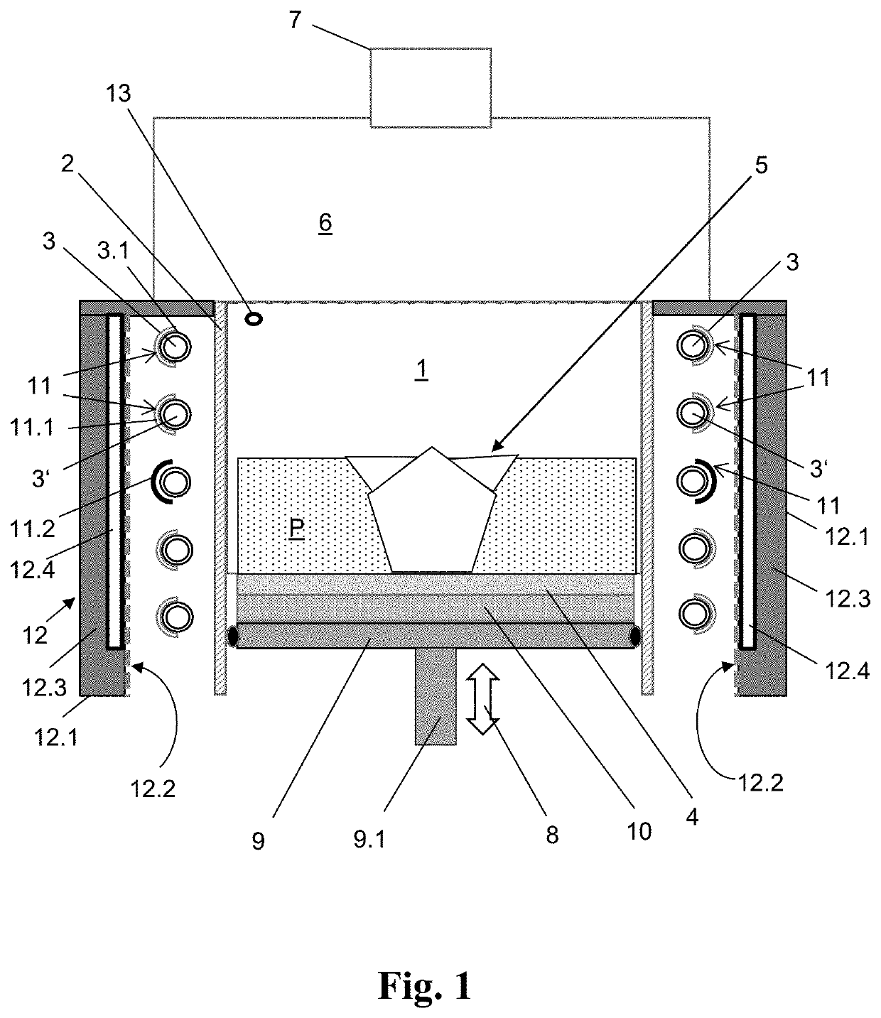
[0036]FIG. 1 is a schematic diagram of an embodiment of the heating device. The construction chamber 1 has a peripheral, cylindrical side wall or partition wall 2 composed of fused silica. A plurality of IR lamps 3, 3′ are mounted on the outside of the partition wall 2 and emit IR radiation towards the powder P or the 3D shaped part 5 on the construction platform 4 in the construction chamber 1. For detecting the temperature of the powder P and of the shaped part 5, the construction chamber 1 has a measuring cell 13 in the form of a thermal imaging camera. Above the construction chamber 1, the process chamber 6 is located, in which units (not shown here) for controlling the build process of the shaped parts 5 are accommodated. At the upper end of the process chamber 6, a laser unit 7 is arranged, shown schematically, which is capable of selectively sintering and / or melting the powder P with a high-energy laser beam issuing therefrom for producing the 3D shaped part 5.

[0037]The powde...


PUM

PropertyMeasurementUnit
wavelengthsaaaaaaaaaa
temperaturesaaaaaaaaaa
temperatureaaaaaaaaaa

Abstract

A heating device for heating a powder during the production of a 3D shaped part. The heating device has an infrared (IR) lamp and a housing in which a construction chamber is provided. The construction chamber is bounded at the bottom by a construction platform for receiving the shaped part and is supported on a support plate. The IR lamp heats the powder during production of the 3D shaped part in the construction chamber. For ensuring an optimized heat transfer to the sintering or melting powder with a particularly homogeneous temperature distribution, a partition wall composed of an IR radiation transparent material is arranged between the construction chamber and the IR lamp.

Description

CROSS REFERENCE TO RELATED APPLICATIONS[0001]This application is a U.S. National Phase filing of International Patent Application No. PCT / EP2019 / 077337 filed on Oct. 9, 2019, which claims the priority of German Patent Application No. 102018125310.9 filed on Oct. 12, 2018. The disclosures of these applications are hereby incorporated by reference in their entirety.TECHNICAL FIELD[0002]The present invention relates to a heating device for heating a powder during the production of a three-dimensional (3D) shaped part, having an IR lamp and having a housing in which a construction chamber is provided which is bounded at the bottom by a construction platform for receiving the shaped part. The construction platform is supported on a support plate.[0003]Furthermore, the invention relates to a method of producing a 3D shaped part using the heating device.[0004]3D shaped parts are generally produced by layering technology and solidification of a loose powder using selective laser sintering o...

Claims


Application Information

Patent Timeline
Patent Type & Authority Applications(United States)
IPC IPC(8): B29C64/295B22F10/20
CPCB29C64/295B33Y30/00B22F10/20B33Y10/00B29C64/153H05B3/265H05B2203/032H05B2203/014Y02P10/25B22F12/38B22F12/90B22F10/28B22F12/44B22F12/13B22F10/50B22F12/30
Inventor WEISS, OLIVERZISSING, HOLGERLOHN, JOHANNESKOPPA, PETER
Owner HERAEUS NOBLELIGHT GMBH
Why Eureka
Try Eureka