
Focused rotary jet spinning devices and methods of use thereof

Pending Publication Date: 2022-03-24
PRESIDENT & FELLOWS OF HARVARD COLLEGE
View PDF0 Cites 0 Cited by
  • Summary
  • Abstract
  • Description
  • Claims
  • Application Information

AI Technical Summary

Benefits of technology

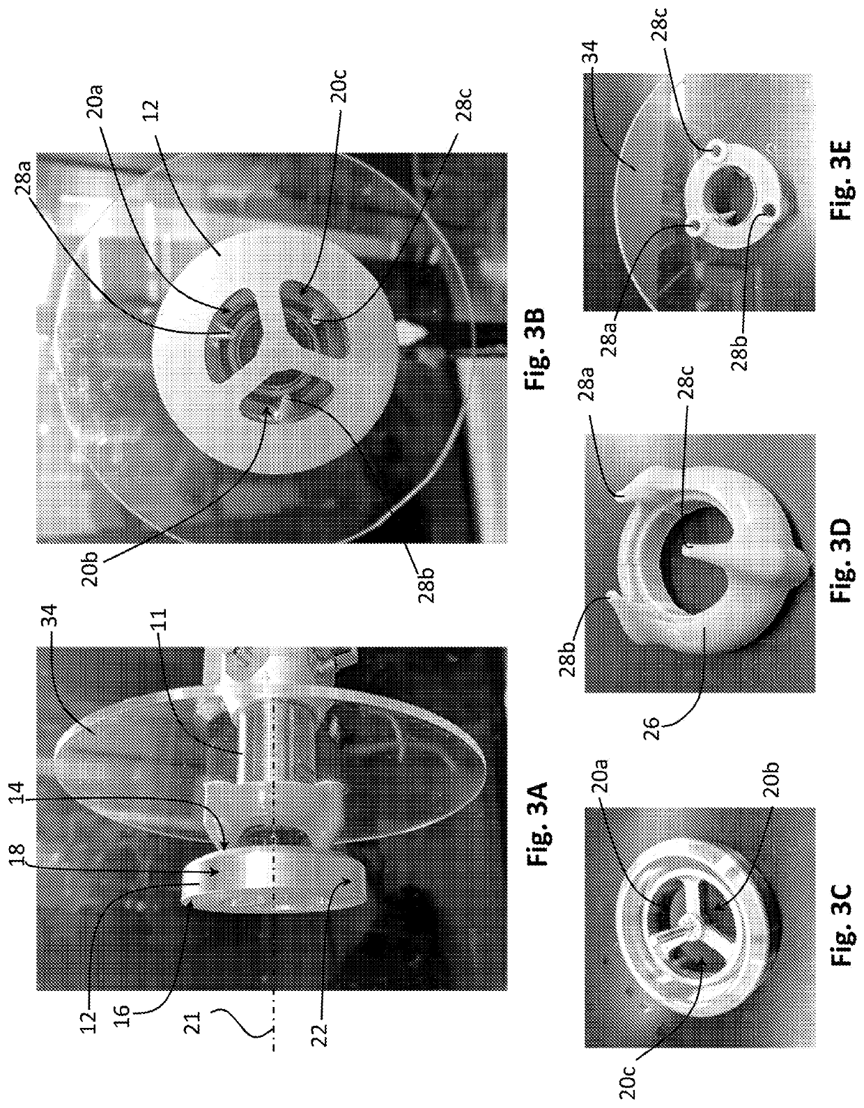
The patent describes a system and method for controlling the focusing of a stream of micron or nanometer dimension polymeric fibers. A flow blocking structure is placed upstream of the gas flow sources to reduce the impact of airflow on focusing. This structure may be stationary or rotate with the reservoir. Additionally, the method includes at least partially blocking flow of gas from upstream of the reservoir to further reduce the impact of airflow on focusing. This results in improved control of the structure of vortices and the deposition of the polymeric fibers, leading to better targeting.

Problems solved by technology

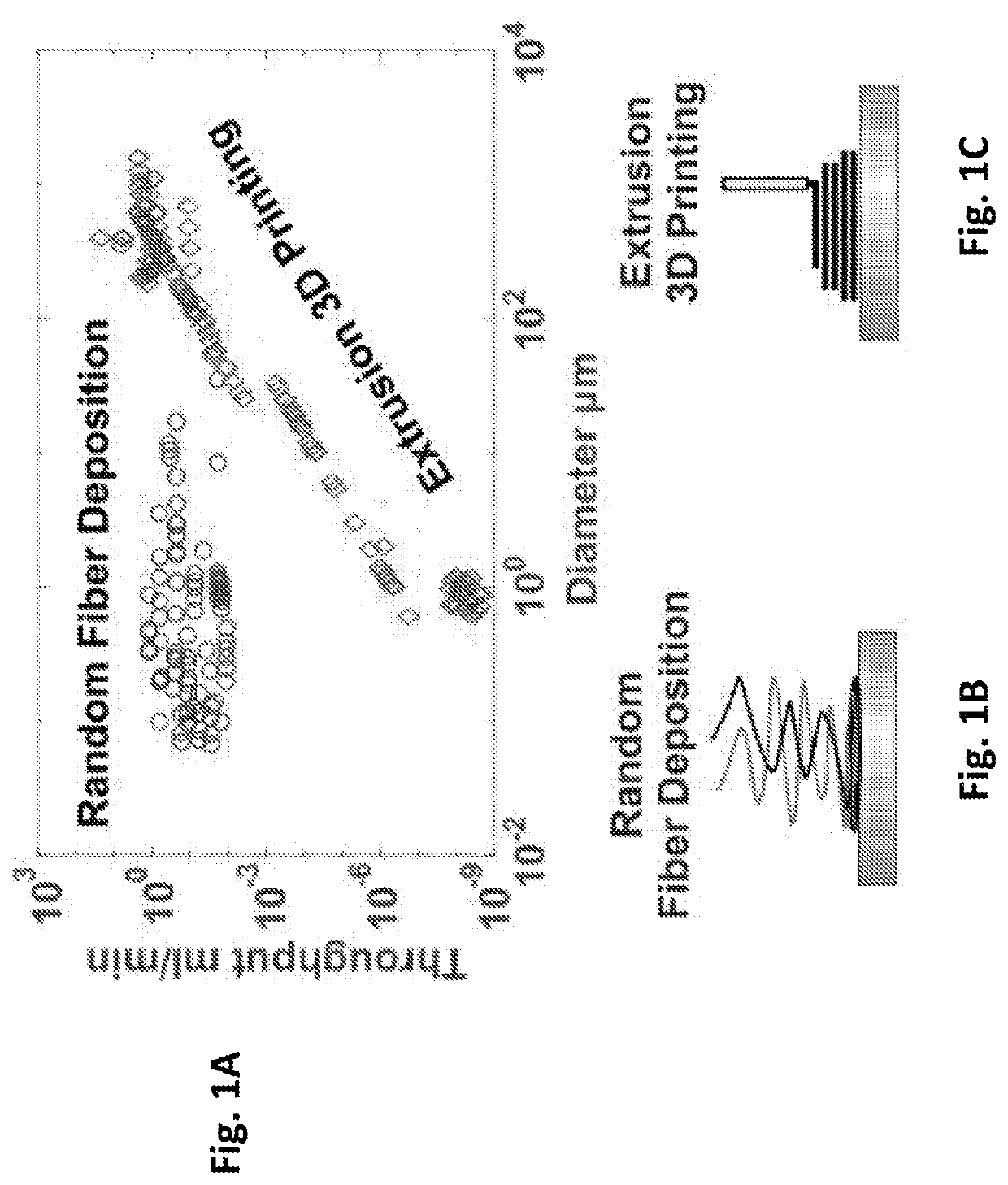
While human beings have a fruitful history of engineering thick fibrous structures with diameters of about 100 μm and above, it remains challenging to engineer fine fibrous structures with diameters of about 10 μm and below with control over fiber alignment and organization with conventional technologies.
In random-FD techniques, such as, for example, melt blowing and electrospinning, fibers approach the target in a randomly arranged cloud and can exhibit poor control over fiber alignment and 3D geometry.
Poor control over the fiber cloud leads to poor control over deposition.
However, extrusion-3DP has low throughput.

Method used


Image

  • Focused rotary jet spinning devices and methods of use thereof
  • Focused rotary jet spinning devices and methods of use thereof
  • Focused rotary jet spinning devices and methods of use thereof

Examples


Embodiment Construction

[0082]In the following description, it is understood that terms such as “top,”“bottom,”“middle,”“outward,”“inward,” and the like are words of convenience and are not to be construed as limiting terms. Reference will now be made in detail to embodiments of the disclosure, which are illustrated in the accompanying figures and examples. Referring to the drawings in general, it will be understood that the illustrations are for the purpose of describing particular embodiments of the disclosure and are not intended to limit the same.

[0083]Whenever a particular embodiment of the disclosure is said to comprise or consist of at least one element of a group and combinations thereof, it is understood that the embodiment may comprise or consist of any of the elements of the group, either individually or in combination with any of the other elements of that group.

[0084]As used herein, the terms “polymer fiber” and “polymeric fiber” refer to a fiber comprising a polymer. The fiber may also includ...


PUM

PropertyMeasurementUnit
Angleaaaaaaaaaa
Angleaaaaaaaaaa
Lengthaaaaaaaaaa

Abstract

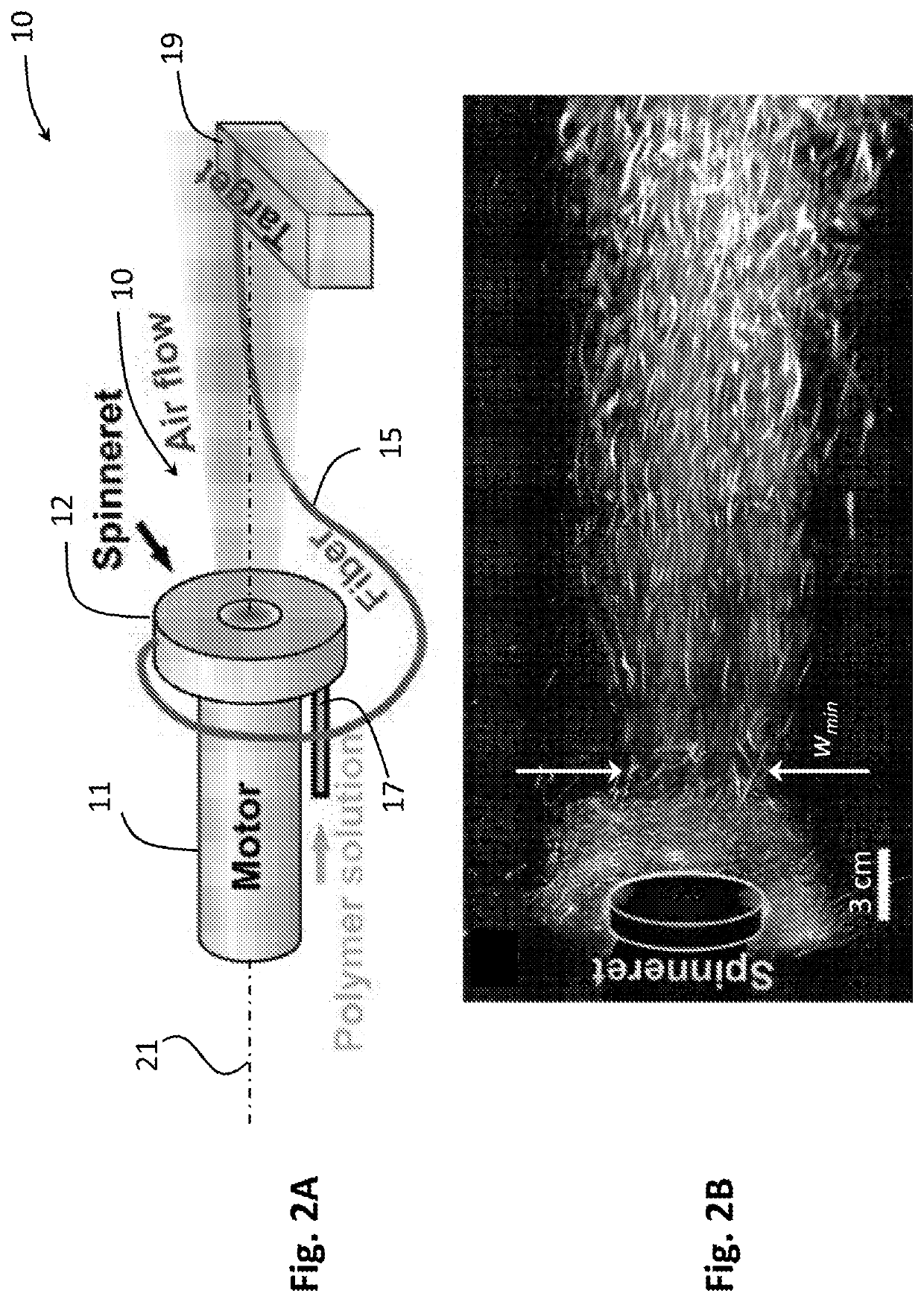
Systems and methods for focused direction deposition of a micron or nanometer dimension polymeric fiber and materials of such fibers are described herein. Systems and methods employ one or more gas flows to entrain and deflect fibers produced by a rotary jet spinning system forming a focused fiber stream. Some embodiments enable control of alignment and distribution of the fibers with a relatively high fiber throughput.

Description

RELATED APPLICATION[0001]This application claims benefit of and priority to U.S. Provisional Application No. 62 / 792,036 filed Jan. 14, 2019, the entire content of which is incorporated by reference herein in its entirety.GOVERNMENT SUPPORT[0002]This invention was made with Government support under grant number DMR-1420570 awarded by the National Science Foundation. The government has certain rights in the invention.TECHNICAL FIELD[0003]Embodiments of the disclosure relate to a directional rotary jet spinning system to manipulate motion of a fiber using air flow convergence.BACKGROUND OF THE INVENTION[0004]Fibrous structures are used by nature and engineers for a plethora of functions: fiber reinforcement, filtration, thermal insulation, actuation control, etc. The realization of these functions critically relies on both the diameter and the 3D organization of the fibers. Many biological tissues consist of small diameter fibers (e.g., micron-scale or nano-scale diameter fibers) arran...

Claims


Application Information

Patent Timeline
IPC IPC(8): D01D5/14D01D5/18
CPCD01D5/14D01D5/18
Inventor LIU, QIHANPARKER, KEVIN KITCHANG, HUIBIN
Owner PRESIDENT & FELLOWS OF HARVARD COLLEGE
Features
  • Generate Ideas
  • Intellectual Property
  • Life Sciences
  • Materials
  • Tech Scout
  • Unparalleled Data Quality
  • Higher Quality Content
  • 60% Fewer Hallucinations
Learn More