Chemical decontamination method

Pending Publication Date: 2022-03-31
HITACHI-GE NUCLEAR ENERGY LTD
View PDF0 Cites 0 Cited by
  • Summary
  • Abstract
  • Description
  • Claims
  • Application Information

AI Technical Summary

Benefits of technology

[0027]According to the present invention, the dose of the steam dryer can be significantly

Problems solved by technology

However, even if the above-mentioned corrosion countermeasures are taken, the presence of a very small amount of metal impurities in the reactor water is unavoi

Method used


Image

  • Chemical decontamination method
  • Chemical decontamination method
  • Chemical decontamination method

Examples


embodiment 1

[0048]The chemical decontamination method of Embodiment 1, which is a suitable embodiment of the present invention, will be described with reference to FIGS. 1 to 10. The chemical decontamination method of this embodiment is applied to a BWR plant.

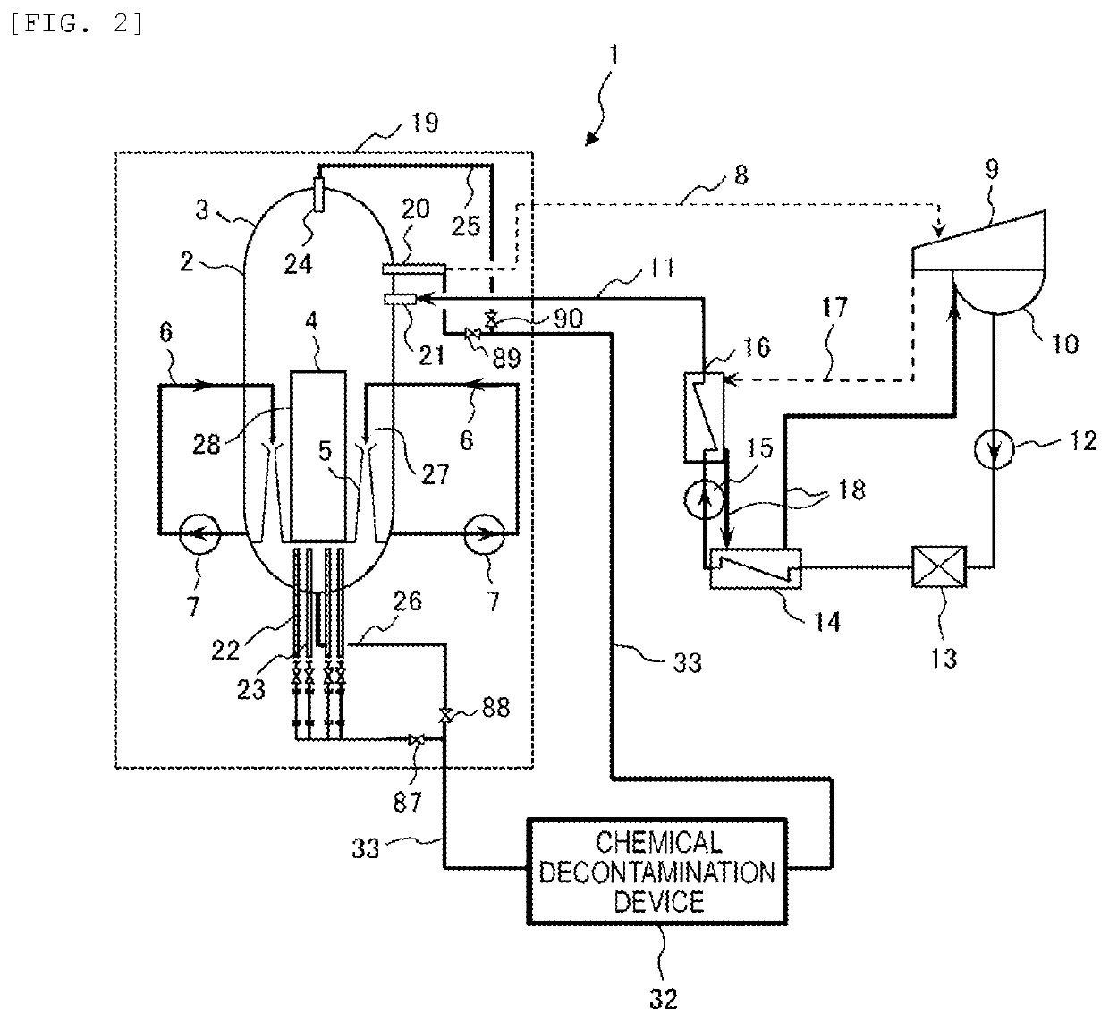
[0049]The schematic configuration of this BWR plant will be described with reference to FIG. 2. A BWR plant 1 includes a nuclear reactor 2, a turbine 9, a condenser 10, a recirculation system, a nuclear reactor cleanup system, a feed water system, and the like. The nuclear reactor 2 is a steam generator and includes a reactor pressure vessel (hereinafter referred to as RPV) 3 having a reactor core 4 built in, and a plurality of jet pumps 5 are installed in an annular downcomer 27 formed between the outer surface of a reactor core shroud 28 surrounding the reactor core 4 in the RPV 3 and the inner surface of the RPV 3. An upper lid 3A (see FIG. 4) is attached to a flange 3B (see FIG. 4) at the upper end of the RPV 3 to seal the RPV 3. As sh...

embodiment 2

[0158]The chemical decontamination method of Embodiment 2, which is another suitable Embodiment of the present invention, will be described with reference to FIGS. 3, 12, and 13. The chemical decontamination method of the present Embodiment is applied to a BWR plant that is subject to decommissioning.

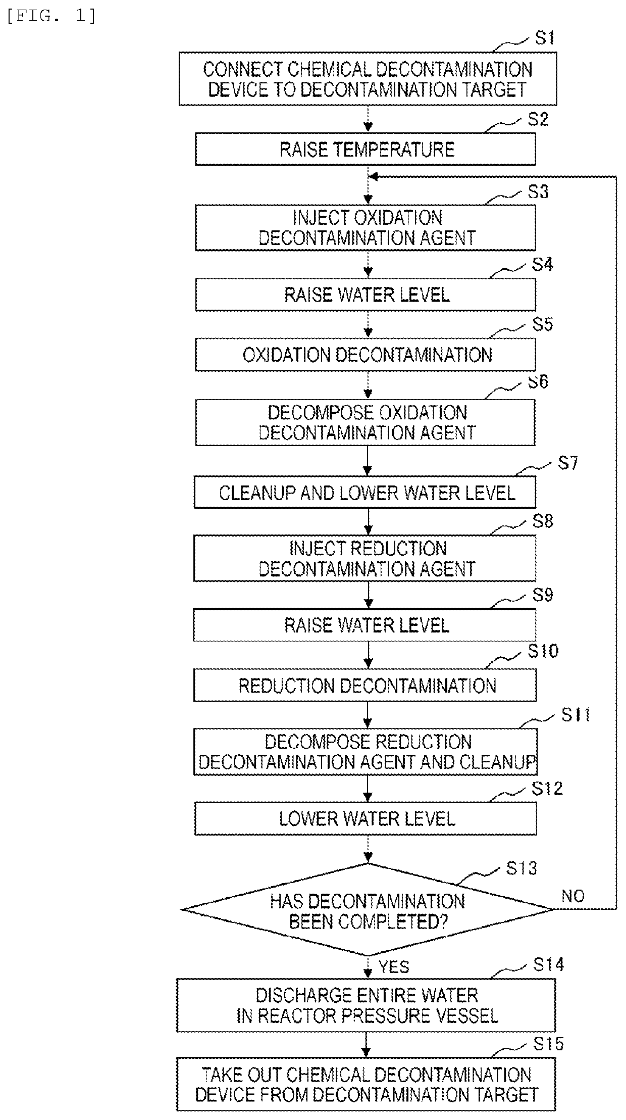
[0159]In the chemical decontamination method of the present Embodiment, each process of steps S1 to S4, S5A, S6, S8, S10A, S11, S13, and S14 shown in FIG. 12 is performed. Before the process of step S1 is performed, all of the fuel assemblies loaded in the reactor core 4 are transferred to the fuel storage pool as described above.

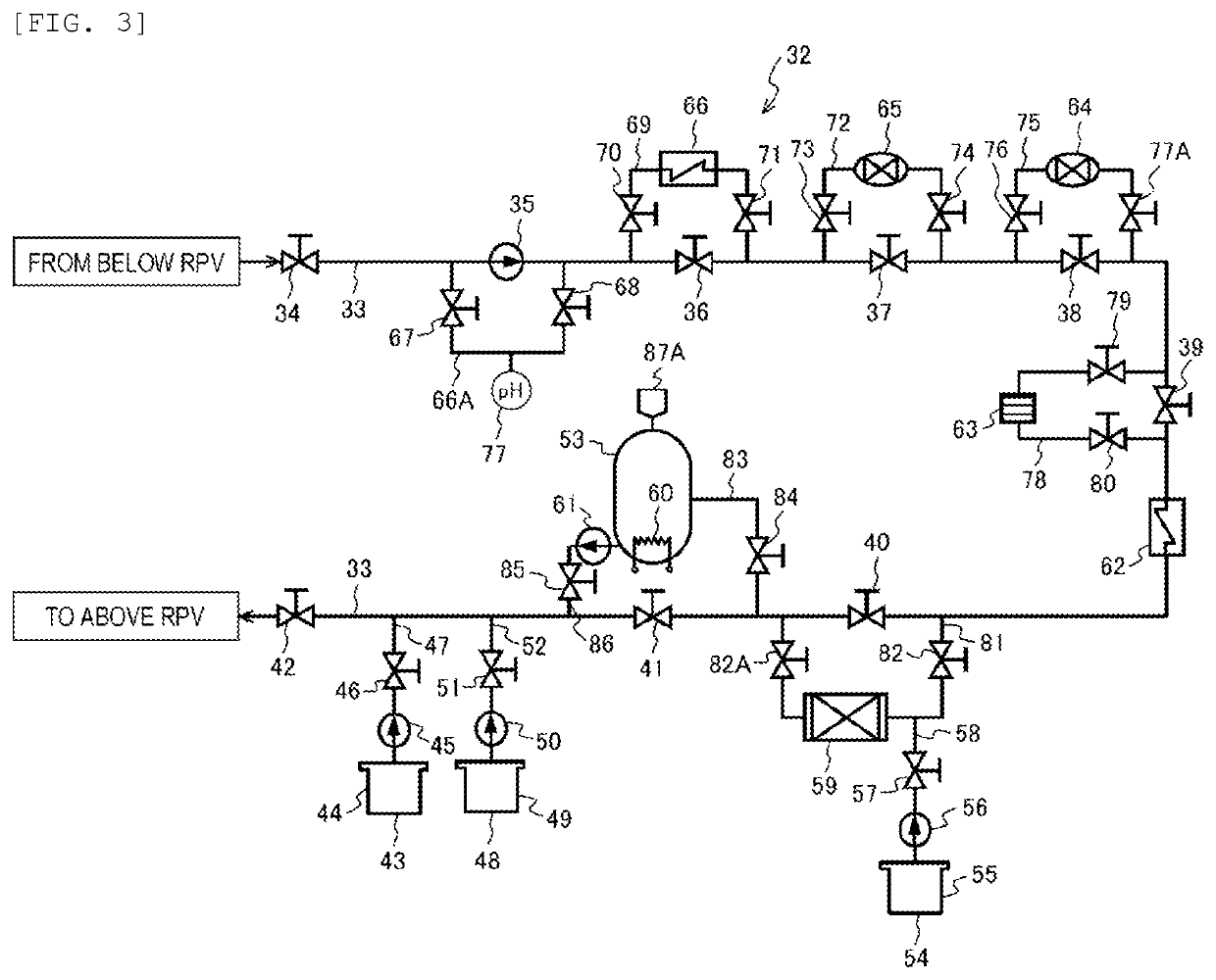
[0160]First, the chemical decontamination device is connected to the decontamination target in the state where the fuel assembly does not exist in the reactor core (step S1). In the process of step S1, one end portion of the circulation pipe 33 of the chemical decontamination device 32 is connected to the decontamination solution distribution pipe of the connec...

embodiment 3

[0187]The chemical decontamination method of Embodiment 3, which is another preferred Embodiment of the present invention, will be described with reference to FIGS. 3, 12, and 14. The chemical decontamination method of the present Embodiment is applied to a BWR plant that is subject to decommissioning.

[0188]In the chemical decontamination method of the present Embodiment, instead of the buffer tank 101 used in the chemical decontamination device of Embodiment 2, any one of a fuel storage pool, a boric acid water injection system (SLC) tank, and an equipment temporary storage pool for storing the steam dryer and gas-water separator is used. In the chemical decontamination method of the present Embodiment, for example, a fuel storage pool is used.

[0189]When a plurality of fuel assemblies are stored in the fuel storage pool before starting the process of step S1 (connection of the chemical decontamination device to the decontamination target) in the chemical decontamination method of t...


PUM


Abstract

A chemical decontamination method capable of improving the decontamination efficiency of chemical decontamination of a steam dryer in the RPV is provided. In particular, the decontamination method includes feeding a chemical decontamination aqueous solution into a reactor pressure vessel in which a steam dryer is arranged, and after chemical decontamination of the steam dryer, the water level of the chemical decontamination aqueous solution existing in the reactor pressure vessel is lowered to a first water level below the lower end of the steam dryer.

Description

CLAIM OF PRIORITY[0001]The present application claims priority from Japanese Patent application serial no. 2020-164910, filed on Sep. 30, 2020, the content of which is hereby incorporated by reference into this application.TECHNICAL FIELD[0002]The present invention relates to a chemical decontamination method for chemically removing radionuclides from the surface of a metal member, and more particularly to a chemical decontamination method suitable for application to a boiling water reactor plant.BACKGROUND ART[0003]For example, a boiling water reactor plant (hereinafter referred to as a BWR plant) includes a nuclear reactor having a reactor core built in a reactor pressure vessel (hereinafter referred to as RPV). The cooling water fed to the reactor core by the recirculation pump (or internal pump) is heated by the heat generated by the nuclear fission of the nuclear fuel material in the fuel assemblies loaded in the reactor core, and a part thereof becomes steam. The steam, in whi...

Claims


Application Information

Patent Timeline
IPC IPC(8): G21F9/28
CPCG21F9/28G21F9/002Y02E30/30
Inventor OOHIRA, TAKASHIYANAGISAWA, SHINTAROOOUCHI, SATOSHIOTA, NOBUYUKIHAMADA, RYOHOSOKAWA, HIDEYUKI
Owner HITACHI-GE NUCLEAR ENERGY LTD
Why Eureka
Try Eureka