Portable analyzer

a portable, analyzer technology, applied in the direction of spectrometry/spectrophotometry/monochromators, instruments, optical radiation measurement, etc., can solve the problems of limited field of view, significant signal loss, shallow depth of field (dof), etc., to reduce cross-contamination, reduce the effect of dof and large fov

Active Publication Date: 2022-04-28
K2R2 LLC
View PDF6 Cites 0 Cited by
  • Summary
  • Abstract
  • Description
  • Claims
  • Application Information

AI Technical Summary

Benefits of technology

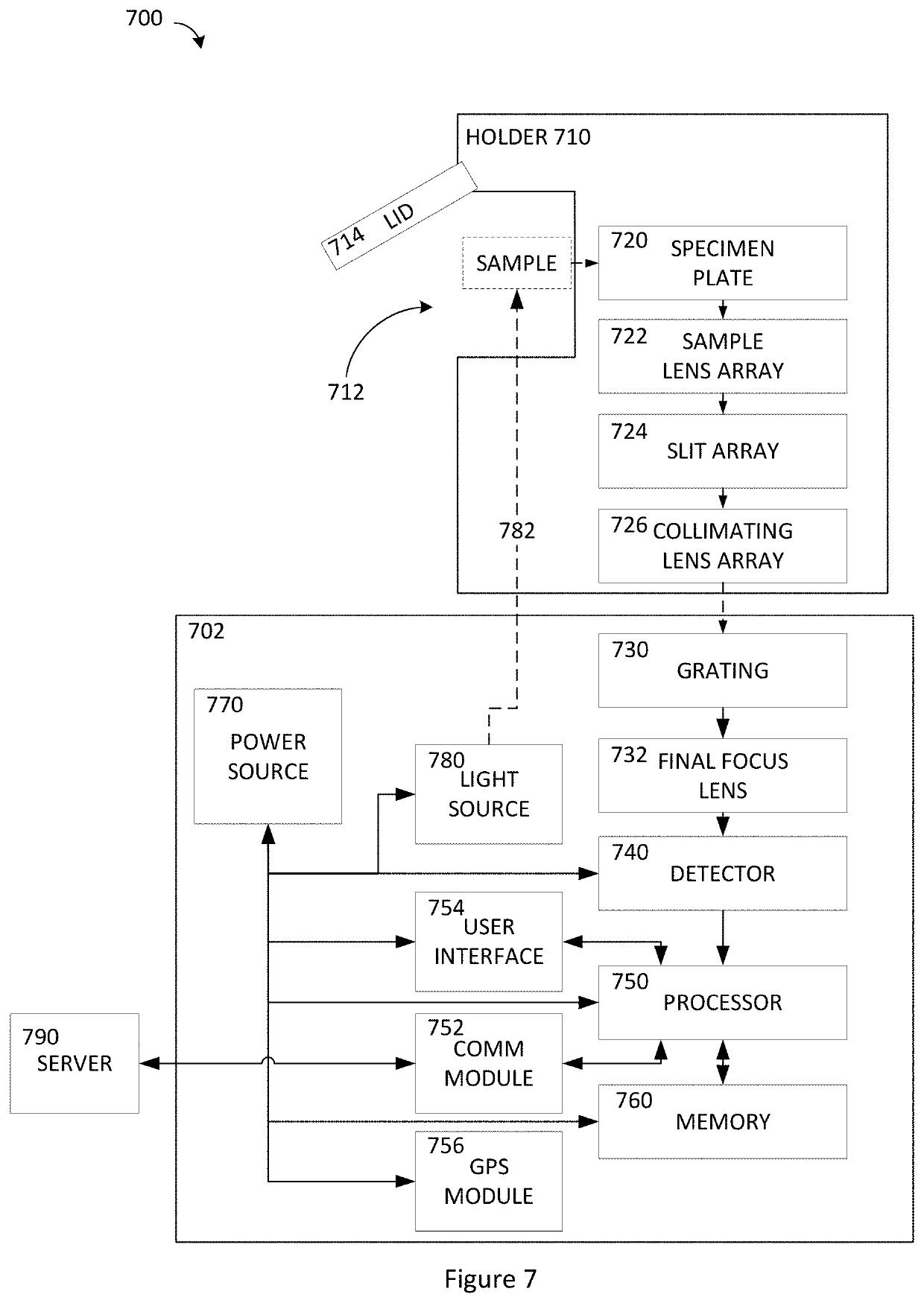
[0006]In certain embodiments, it is desirable to provide a robust, compact Raman spectrometer that utilizes a single-use sample holder to eliminate cross-contamination and replaces the conventional optical elements with arrays of collection lenses, slits, and collimation lenses so as to achieve a larger FOV, greater DOF, and increased light capture and provide a spatially averaged determination of material characteristics across a sample without scanning the sample.

Problems solved by technology

Conventional Raman spectrometers suffer from a number of drawbacks including a limited Field of View (FOV), a high numerical aperture (NA) that inherently results in a shallow Depth of Field (DOF), and a significant loss of signal due to the use of a single narrow slit.

Method used


Image

  • Portable analyzer
  • Portable analyzer
  • Portable analyzer

Examples


embodiments

[0079]A1. An apparatus for analysis of a sample, comprising: a frame having a first axis; a sample holder coupled to the frame and disposed on the first axis; a transmissive diffraction grating coupled to the frame and disposed along the first axis such that light traveling along the first axis from the sample holder passes through the grating in a first direction; and a source coupled to the frame and configured to emit a first light to pass through the grating in a second direction that is opposite the first direction.

[0080]A2. The apparatus of A1, further comprising: a lens coupled to the frame; and a spatial filter coupled to the frame; wherein the lens and spatial filter are disposed along the first optical axis.

[0081]A3. The apparatus of A1, wherein a portion of the first light emitted by the source is diffracted by the grating to travel parallel to the first optical axis.

[0082]A4. The apparatus of A3, wherein: the light emitted by the source is monochromatic; the diffracted p...


PUM

PropertyMeasurementUnit
diameteraaaaaaaaaa
anglesaaaaaaaaaa
Raman spectroscopyaaaaaaaaaa

Abstract

An apparatus for analysis of a sample of a material is disclosed. The apparatus includes a holder configured to accept the sample. The holder includes a sample plate having a first surface configured to contact the accepted sample and a sample lens array that comprises a plurality of focusing elements.

Description

CROSS-REFERENCE TO RELATED APPLICATIONS[0001]Not applicable.STATEMENT REGARDING FEDERALLY SPONSORED RESEARCH OR DEVELOPMENT[0002]Not applicable.BACKGROUNDField[0003]The present invention generally relates to the use of Raman spectroscopy to identify attributes of a material.Description of the Related Art[0004]Raman spectroscopy, named after Indian physicist C. V. Raman, is a spectroscopic technique used to identify materials. A source of monochromatic light illuminates a sample. The photons of the source light excite the molecules of the sample, which then emit photons that will be at a higher or lower energy level, compared to the incident photons, depending on the vibrational modes of the molecules of the sample. Every molecule has a characteristic “fingerprint” based on its structure. Comparison of the results generated by a sample to a library of material fingerprints enables the determination of the materials in the sample.[0005]Conventional Raman spectrometers suffer from a nu...

Claims


Application Information

Patent Timeline
Patent Type & Authority Applications(United States)
IPC IPC(8): G01N21/65
CPCG01N21/65G01N2201/0221G01N2021/651G01J3/44G01J3/0264G01J3/0256G01J3/0208G01J3/0275
Inventor KAY, ROBERT LROSS, GRAHAM
Owner K2R2 LLC
Why Eureka
Try Eureka