
Battery connections and metallized film components in energy storage devices having internal fuses

a technology of energy storage devices and metallized film components, which is applied in the direction of batteries, sustainable manufacturing/processing, wound/folded electrode electrodes, etc., can solve the problems of thermal runaway events within the target battery cell, the subject battery, the device/implement within which it is present, and the surrounding environment, so as to reduce the flow of current, reduce the weight, and improve the effect of weight and cos

Pending Publication Date: 2022-04-28
SOTERIA BATTERY INNOVATION GRP INC
View PDF3 Cites 0 Cited by
  • Summary
  • Abstract
  • Description
  • Claims
  • Application Information

AI Technical Summary

Benefits of technology

The patent describes a new design for battery cells that has several advantages. First, it includes a structure that breaks the conductive pathway when there is an internal short, reducing the flow of current and potentially preventing heat from accumulating. This design also provides a way to make the battery lighter and less expensive to manufacture, transport, and use. Next, it introduces a thin film base current collector that prevents thermal runaway during a short circuit. Additionally, the patent presents a method to use flammable organic electrolytes without causing ignition. Finally, it discusses how the design allows for a sufficient amount of conductive contact and can be folded to create a compact battery that generates power efficiently.

Problems solved by technology

Within the present disclosure, while it may be possible to measure a larger current, the delivery time for such a current is sufficiently short such that the total energy delivered is very small and not enough to generate enough heat to cause a thermal runaway event within the target battery cell.
This resultant measurement can increase the temperature of a 1-gram section of the subject battery by about 300° C., a temperature high enough to not only melt the conventional separator material present therein, but also drive the entire cell into a runaway thermal situation (which, as noted above, may cause the aforementioned compromise of the electrolyte materials present therein and potential destruction of not only the subject battery but the device / implement within which it is present and the surrounding environment as well.

Method used


Image

  • Battery connections and metallized film components in energy storage devices having internal fuses
  • Battery connections and metallized film components in energy storage devices having internal fuses
  • Battery connections and metallized film components in energy storage devices having internal fuses

Examples


example 1

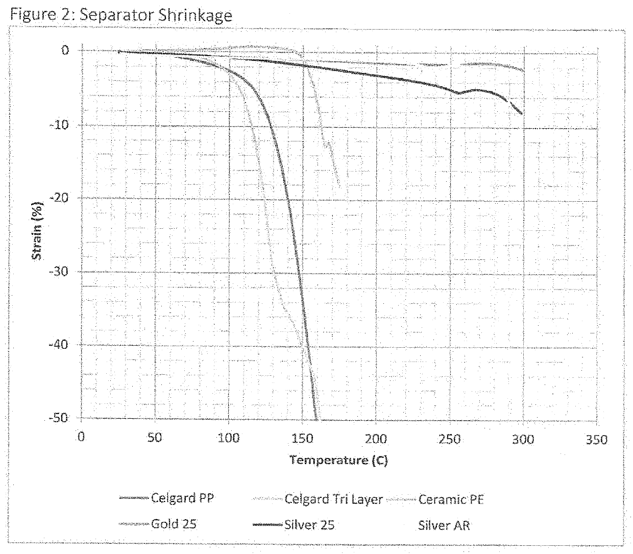
[0087]Polypropylene lithium battery separator material was obtained from MTI Corporation. The material was manufactured by Celgard with the product number 2500. The thickness, areal density and resistance were measured, which are shown in Table 1, below. The separator was then touched with a hot soldering iron in the same way as Example 1. Touching the thermometer to the current collector created a small hole. The diameter was measured and included in Table 1. The thickness, areal density and resistance were measured. The material was placed in an oven at 175° C. for 30 minutes and the shrinkage measured. A photograph was taken and included in FIG. 7A.

example 2

[0088]Ceramic coated polyethylene lithium battery separator material was obtained from MTI Corporation. The thickness, areal density and resistance were measured, which are shown in Table 1, below. The separator was then touched with a hot soldering iron in the same way as Example 1. Touching the soldering iron to the current collector created a small hole. The diameter was measured and included in Table 1. The thickness, areal density and resistance were measured. The material was placed in an oven at 175° C. for 30 minutes and the shrinkage measured. A photograph was taken and included in FIG. 7B.

example 3

[0089]Ceramic coated polypropylene lithium battery separator material was obtained from MTI Corporation. The thickness, areal density and resistance were measured, which are shown in Table 1, below. The separator was then touched with a hot soldering iron in the same way as Example 1. Touching the soldering iron to the current collector created a small hole. The diameter was measured and included in Table 1. The thickness, areal density and resistance were measured. The material was placed in an oven at 175° C. for 30 minutes and the shrinkage measured. A photograph was taken and included in FIG. 7C.


PUM

PropertyMeasurementUnit
temperaturesaaaaaaaaaa
shrinkageaaaaaaaaaa
temperaturesaaaaaaaaaa

Abstract

A lithium battery cell with an internal fuse component and including needed tabs which allow for conductance from the internal portion thereof externally to power a subject device is provided. Disclosed herein are tabs that exhibit sufficient safety levels in combination with the internal fuse characteristics noted above while simultaneously displaying pull strength to remain in place during utilization as well as complete coverage with the thin film metallized current collectors for such an electrical conductivity result. Such tabs are further provided with effective welds for the necessary contacts and at levels that exhibit surprising levels of amperage and temperature resistance to achieve the basic internal fuse result with the aforementioned sufficient conductance to an external device. With such a tab lead component and welded structure, a further improvement within the lithium battery art is provided the industry.

Description

CROSS-REFERENCE TO RELATED APPLICATIONS[0001]This application is a continuation-in-part of pending U.S. patent application Ser. No. 15 / 927,075, filed on Mar. 28, 2018, which is a continuation-in-part of pending U.S. patent application Ser. No. 15 / 700,077, filed on Sep. 9, 2017, the entirety of both applications herein being incorporated by reference.FIELD OF THE INVENTION[0002]The present disclosure relates to improvements in the structural components and physical characteristics of lithium battery articles. Standard lithium ion batteries, for example, are prone to certain phenomena related to short circuiting and have experienced high temperature occurrences and ultimate firing as a result. Structural concerns with battery components have been found to contribute to such problems. Improvements provided herein include the utilization of thin metallized current collectors (aluminum and / or copper, as examples), high shrinkage rate materials, materials that become nonconductive upon ex...

Claims


Application Information

Patent Timeline
Patent Type & Authority Applications(United States)
IPC IPC(8): H01M10/42H01M10/0525H01M10/04H01M10/0587H01M10/0565H01M50/107H01M50/403H01M50/449
CPCH01M10/4235H01M10/0525H01M10/0431H01M10/0587H01M2200/103H01M50/107H01M50/403H01M50/449H01M10/0565H01M4/661H01M4/667H01M4/668H01M50/44H01M50/489Y02E60/10Y02P70/50H01M50/583
Inventor MORIN, BRIAN G.HU, CARL C.
Owner SOTERIA BATTERY INNOVATION GRP INC
Learn More