
Recompressed transcritical cycle with vaporization in cryogenic or low-temperature applications, and/or with coolant fluid

Pending Publication Date: 2022-06-16
SAIPEM SPA
View PDF0 Cites 0 Cited by
  • Summary
  • Abstract
  • Description
  • Claims
  • Application Information

AI Technical Summary

Benefits of technology

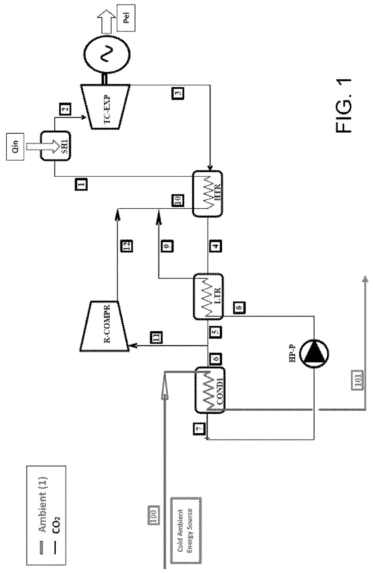
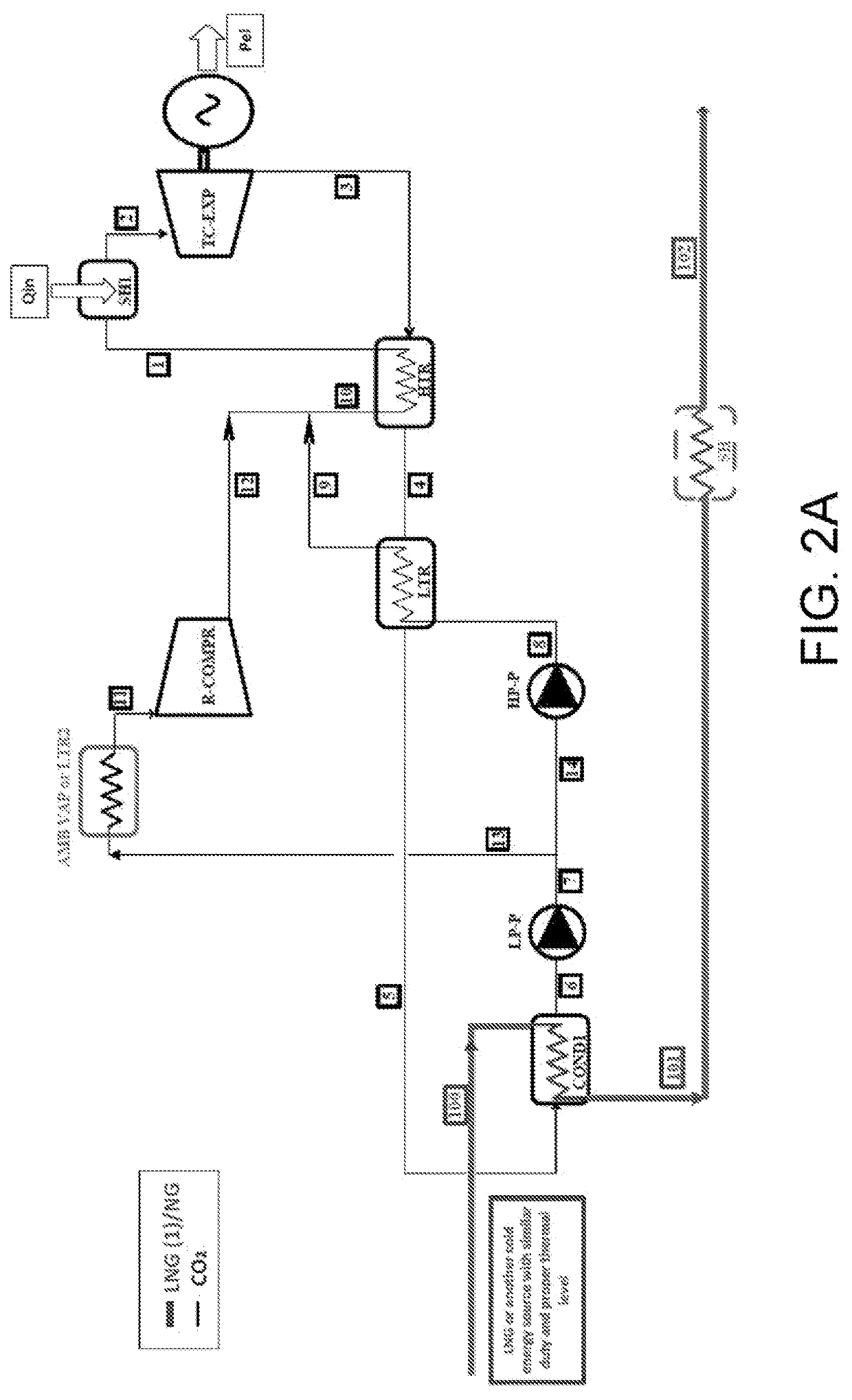
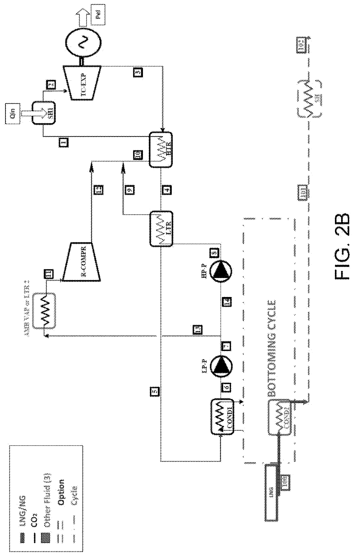
The invention is a process for regasifying a fluid and generating electrical energy. A line is also described that allows for this process. The technical effects of this invention include the ability to generate energy from liquefied gas and the improved efficiency of energy generation from waste heat.

Problems solved by technology

The (SCV) technology results in a consumption of fuel gas equal to about 1.5% of the processed gas and generates carbon dioxide which lowers the pH of the water bath, requiring treatments with caustic soda and thus causing an emission of CO2 into the atmosphere of about 50,000 t / year in order to regasify 139 t / h of LNG.
Moreover, this does not allow a reasonable system stability:given the high critical pressure of the CO2 (73.8 bar A), the benefits due to the high temperature and input pressure to the expansion turbine are reduced by the smaller maximum expansion ratio attainable, and therefore by the power which can be extracted from the cycle;also having available a cold well at lower temperature and desiring to utilize a very high maximum pressure (up to 300 bar A), the employment of a condensation pressure less than about 50 bar A (and therefore a condensation temperature less than 15° C.) would result in a much greater complexity of the (inter-refrigerated multi-stage) recompressor due to the too high compression ratio;the systems operating with gaseous steps alone require significant storage volumes to manage the circulating flows.
Using a not-recovered CO2 cycle thus means extracting mechanical energy in a poorly efficient manner from a system which would potentially be more efficient with a recuperator or recompressor.
Therefore, the conventional and / or already known technologies do not generally allow the electrical energy required for the plant to be generated and result in the loss of a large quantity of energy in the form of frigories.

Method used


Image

  • Recompressed transcritical cycle with vaporization in cryogenic or low-temperature applications, and/or with coolant fluid
  • Recompressed transcritical cycle with vaporization in cryogenic or low-temperature applications, and/or with coolant fluid
  • Recompressed transcritical cycle with vaporization in cryogenic or low-temperature applications, and/or with coolant fluid

Examples


Embodiment Construction

[0044]The present invention is particularly described in relation to regasifying liquefied natural gas (LNG), but it is equally applicable for regasifying or vaporizing other liquefied fluids stored at low temperatures (lower than about 0° C.) or at cryogenic temperatures (lower than −45° C.)

[0045]For example, the present invention is applied for regasifying a liquefied gas selected from the group which comprises, for example: air, nitrogen, commercially available hydrocarbon compounds such as alkanes, including for example propane and butane, or alkenes, including for example ethylene and propylene.

[0046]The terms “evaporation” and “vaporization”, which are applicable to LNG, are to be intended as synonyms in the following description.

[0047]Moreover, “liquefied natural gas”, later also referred to as “liquefied gas”, in the present description means a liquid obtained from natural gas after suitable refining and dehydrating processes and next cooling and condensation steps.

[0048]Mor...


PUM


Abstract

A process for regasifying a fluid and generating electrical energy includes subjecting an operating fluid to 1) pumping, the pumping step including a low pressure pumping step 1a) and a high pressure pumping step 1b), 2) heating in a recuperator to obtain a heated flow, the heating step including a low temperature heat recovery step 2a) and a high temperature heat recovery step 2b), 3) further heating through a high temperature source to obtain a further heated flow, 4) expanding in a turbine, with generation of electrical energy to obtain an expanded flow, 5) cooling by heat exchange to obtain a cooled flow, and 6) condensing the flow of the operating fluid and regasifying the fluid. After low pressure pumping, a portion of the flow of the operating fluid is subjected to recompression to obtain a flow combined with the flow of the operating fluid obtained from step 2a).

Description

TECHNICAL FIELD OF THE INVENTION[0001]The present invention applies to the energy field, in particular for improving the energy efficiency of plants for regasifying liquefied natural gas.BACKGROUND ART[0002]Technologies are known for regasifying liquefied gases, such as liquefied natural gas (LNG), for example.[0003]The liquefied natural gas is a mixture of natural gas mainly consisting of methane and, to a lesser extent, of other light hydrocarbons, such as ethane, propane, iso-butane, n-butane, pentane, and nitrogen, which is converted from the gaseous state, in which it is at ambient temperature, to the liquid state, at about −160° C., to allow the transport thereof.[0004]Liquefaction plants are located close to natural gas generating sites, while regasifying plants (or “regasifying terminals”) are located close to the users.[0005]Most of the plants (about 85%) is located onshore, while the remaining part (about 15%) is located offshore on platforms or ships.[0006]It is common fo...

Claims


Application Information

Patent Timeline
IPC IPC(8): F17C9/02F17C5/06
CPCF17C9/02F17C5/06F17C2265/05F17C2221/033F17C2223/0161F17C2260/046F17C2227/0135F17C2227/0323F17C2227/0327F17C2227/0362F17C2223/033F01K25/103F01K19/04F01K7/32F22B3/08
Inventor SBARSI, MASSIMILIANOAURILIO, LUCIOFANTOLINI, ANTON MARCODE RINALDIS, SALVATORE
Owner SAIPEM SPA
Learn More